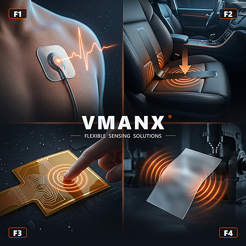
A PET-based composite sensing platform that combines printed EEG electrodes on the skin-contact layer with a reflective optical PPG module on a black FPC, routed through one compact Type-C interface.

PLATFORM VALUE
Two modalities, one forehead interface
A composite construction brings electrical and optical sensing into one registered, flexible assembly.
01 One placement workflow
Electrical contacts and the optical head are registered in one flexible assembly, reducing separate sensor placement and cable routing.
02 Two complementary signals
EEG captures cerebral electrical activity; reflective PPG captures pulsatile optical changes for synchronized trend analysis.
03 Separated sensing zones
The white EEG face and black optical FPC keep the electrode and optical paths physically defined while sharing the same forehead platform.
04 OEM-configurable interface
Electrode pattern, LED/photodiode layout, tail length, connector pinout and skin-interface stack are released per customer drawing.
Two sensing faces, one integrated stack
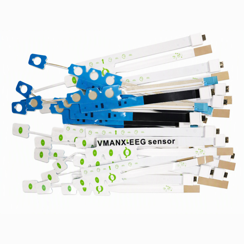
The user-provided samples show a white PET electrode layer and a black optical FPC sharing one flexible forehead format.
STRUCTURE MAP
01 EEG skin-contact layer
PET film with printed conductive traces and customer-defined electrode pads. Ag/AgCl and hydrogel-seven contact systems are project options.
02 Optical isolation layer
Black masking and controlled apertures separate the LED emission path from the photodetector receive path and reduce ambient-light crosstalk.
03 PPG component FPC
Black flexible circuit carrying the visible LED / optical detector packages, local passives and routed conductors.
04 Interconnect & strain relief
Type-C mechanical connector with reinforced tail transition. Pinout and electrical protocol are defined by the OEM host system.
Electrical activity + optical pulse trend
Two signal chains remain physically distinct at the sensor and synchronize in the host system.
EEG
Microvolt biopotential
Skin electrodes → low-noise differential AFE → filtering → EEG channel
PPG TX
Pulsed optical emission
Red / NIR LED option → tissue illumination → diffuse reflectance
PPG RX
Photocurrent detection
Reflected light → photodiode → transimpedance AFE → ambient subtraction
FUSION
Time-aligned trends
Host-side synchronization of EEG and PPG waveforms; algorithm owned by the finished-device manufacturer.
From optical FPC subassembly to integrated product
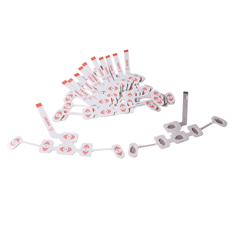
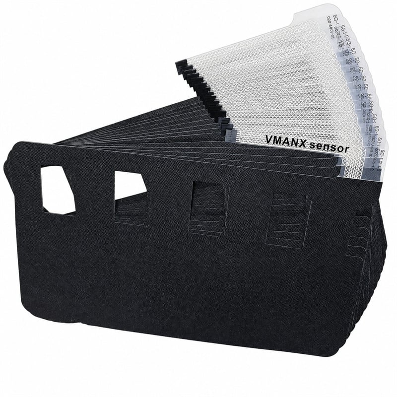
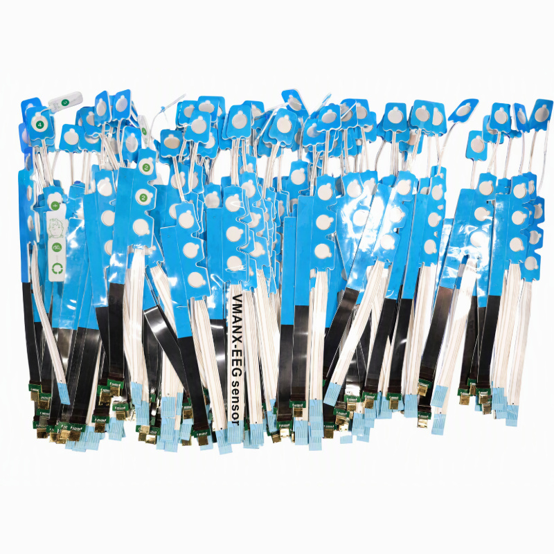
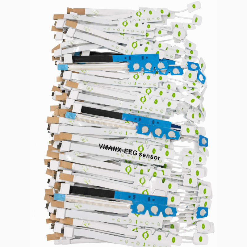
All six supplied images are used below. The first two document the black optical FPC before lamination; the remaining four document integrated builds.
PPG SUBASSEMBLY
Optical FPC before lamination
Black flexible circuits with component apertures, local passives and Type-C connector builds shown as a production batch.
PPG SUBASSEMBLY
Emitter / detector zone visibility
Individual strips reveal the component side, optical apertures, routed traces and connector reinforcement before the EEG layer is added.
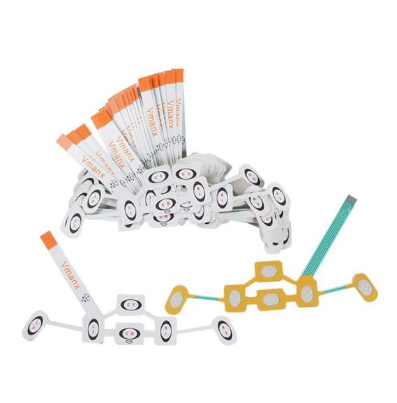
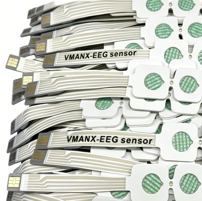
FINAL ASSEMBLY
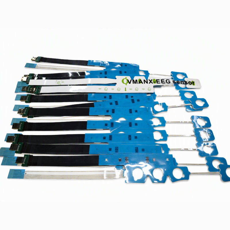
EEG + PPG integrated production lot
White PET electrode substrates and black optical FPCs are present in one mixed lot, showing the transition from subassembly to complete product.
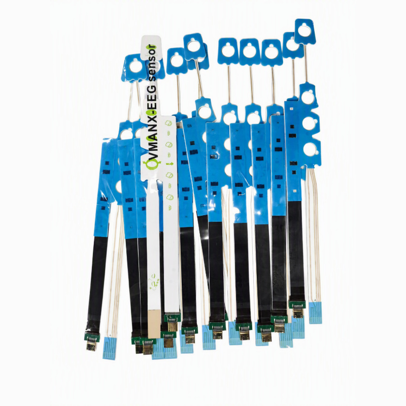
FINAL ASSEMBLY
Registered dual-modal construction
Completed samples show the EEG electrode geometry, black optical section and connector region aligned on one flexible forehead format.
FINAL ASSEMBLY
Optical side and EEG leads together
The production spread shows component-side optical FPCs integrated with the electrode carrier and long printed leads.
SYSTEM OVERVIEW
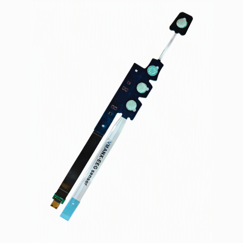
Two sensing faces, one interface
The sample overview makes the architecture explicit: EEG electrode face and optical PPG FPC share one Type-C-connected platform.
Six-stage hybrid assembly flow
The flow combines printed-electrode processing with conventional FPC component assembly, then aligns both systems during lamination.
PET Preparation
Clean, corona-treat and register the film web.
EEG Trace Printing
Screen-print conductive and Ag/AgCl regions.
Optical FPC Assembly
SMT-place emitters, detector and passives.
Inspection & Test
AOI, continuity, LED and detector screening.
Precision Lamination
Align EEG, optical mask, FPC and adhesive.
Final Integration
Die-cut, attach Type-C, inspect and pouch.
Electrical and optical qualification framework
Reference values are not released product guarantees. Final limits are frozen only in the approved OEM specification.
EEG ELECTRICAL PATH
| PET substrate | Confirmed | Flexible PET film |
| Electrode geometry | Confirmed | Customer-defined; sample shows multi-pad layout |
| Conductive system | Design option | Printed Ag / AgCl stack |
| DC offset voltage | Reference target | <= 100 mV; project target <= 20 mV |
| AC impedance @ 10 Hz | Reference target | <= 2 kohm; project target <= 800 ohm |
| Offset drift | Reference target | <= 150 uV/s; project target <= 50 uV/s |
| Intrinsic noise | Reference target | <= 150 uV p-p, 0.15-100 Hz |
| Trace resistance | Design target | <= 200 ohm per path |
| Channel matching | Design target | <= 15% impedance deviation |
PPG OPTICAL PATH
| Optical mode | Confirmed | Reflective PPG, same-side emitter / detector |
| Emitter channels | Visible / configurable | Multiple LED apertures on black FPC |
| Nominal wavelengths | Reference option | Red ~660 nm + NIR ~880-940 nm; TBC |
| Detector | Project-specific | Silicon photodiode / optical AFE input; TBC |
| LED drive | Host dependent | Pulsed current, amplitude and duty cycle TBC |
| Ambient cancellation | AFE requirement | LED-off sample + DC subtraction |
| Flicker rejection | AFE requirement | 50 / 60 Hz correlated sampling / filtering |
| Motion artefact control | System requirement | Mechanical coupling + host algorithm |
| Output claim | Scope limit | PPG waveform / oxygenation trend only |
Materials, interface and custom windows
| Platform construction | PET EEG layer + black optical FPC + adhesive stack |
| Connector | Type-C mechanical interface; custom pinout / protocol |
| Electrode count & spacing | Custom per customer montage |
| Optical window geometry | LED / detector spacing custom per optical stack |
| Tail length | Custom to host-device architecture |
| Bend radius | Design target >= 10x total stack thickness |
| Strain relief | Reinforced connector and sensor-neck transitions |
| Wear time | TBC after adhesive and biocompatibility validation |
| Sterilisation / supply state | TBC per released project |
DESIGN WINDOW
EEG — Pad map & reference location
PPG — LED / detector geometry
HOST — Pinout, protocol & sampling
SKIN — Gel, adhesive & wear time
PACK — Pouch, tray & labelling
A Type-C shell does not imply USB protocol. Electrical definition remains project-specific.
One platform across four clinical workflows
ICU
Continuous multimodal trending
Synchronized EEG and optical waveform acquisition at the bedside.
OPERATING ROOM
Anaesthesia monitoring interface
One placement workflow before induction; host algorithm remains external.
SLEEP LAB
Overnight neuro-respiratory context
Low-profile forehead placement for long-duration waveform collection.
NEUROLOGY
Recovery and ambulatory studies
Paired electrical and pulsatile optical trends in step-down workflows.
Six interfaces we release to customer specification
EEG montage
Pad count, spacing, branch shape and reference location
Optical geometry
LED count, wavelength option, detector spacing and mask
Electrical interface
Type-C pin map, local passives and host AFE matching
Mechanical stack
PET gauge, FPC thickness, adhesive, gel and cover layer
Cable architecture
Tail length, bend zones, strain relief and connector shell
Verification pack
Drawing, BOM, inspection plan and project test report

Dongguan Zhongman Industrial Co., Ltd.
 EN
EN