EN
EN

PI Copper vs PET Silver FPC: Which to Choose | VMANX
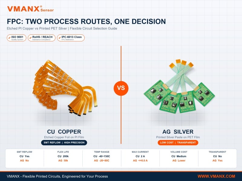
Two process routes for flexible printed circuits: etched PI copper (left) and printed PET silver (right).
VMANX, an ISO 9001-certified printed electronics manufacturer in Dongguan, China, builds flexible printed circuits on two fundamentally different process routes: etched PI copper foil (VMX-FPC-CU) and screen-printed PET silver paste (VMX-FPC-AG). Engineers choose between them whenever a new flexible interconnect enters design review, because the decision fixes cost, component mounting method and service temperature for the life of the product. One route subtracts material, the other adds it — and that single difference cascades into every specification that follows.
Two Routes, Two Manufacturing Philosophies
The distinction is not a grade difference. It is a manufacturing philosophy difference, and each philosophy carries its own physics.
Subtractive etching (PI copper) starts with a copper foil fully laminated to polyimide film. Photoresist is exposed to the circuit pattern, then chemical etchant dissolves every trace of copper that is not part of the design. What remains is rolled-annealed copper — a true metal conductor with metallic conductivity, solderable at reflow temperature, and dimensionally precise down to 75/75 μm line and space.
Additive printing (PET silver) starts with a bare polyester film. Conductive silver paste is screen-printed directly onto the substrate in the shape of the circuit, then thermally cured. Nothing is removed, no etchant is consumed, and no photo-tooling is required. The conductor is a cured composite of silver particles in a polymer binder — electrically sufficient for signal work, but not a solid metal foil.
That structural difference explains everything downstream: why one accepts reflow soldering and the other does not, why one survives +150 °C and the other stops at +80 °C, and why one can be made optically transparent while the other never can.
Process A — Etched PI Copper (VMX-FPC-CU)
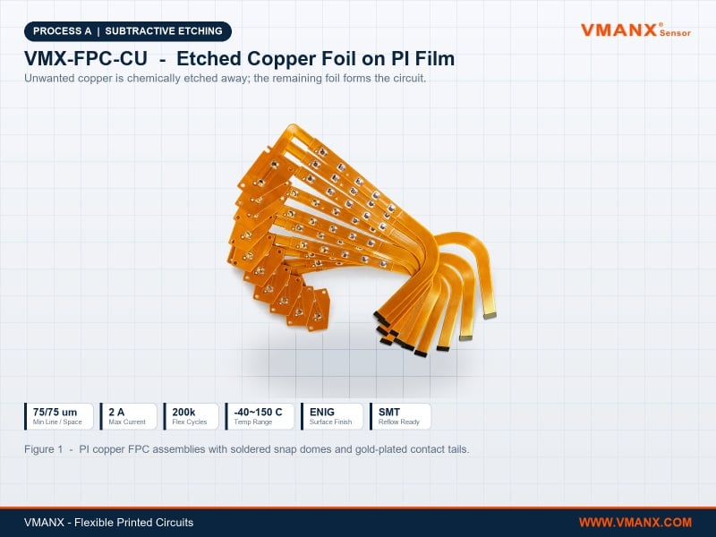
Figure 1 — PI copper FPC assemblies with soldered snap domes and gold-plated contact tails.
Precision and Component Density
Rolled-annealed copper on polyimide reaches 75/75 μm minimum line and space as standard, tightening to 50/50 μm with 0.5 oz copper. That resolution supports fine-pitch connectors and dense component fields that printed silver simply cannot resolve.
Because the conductor is solid metal, impedance can be controlled to 50 Ω single-ended or 100 Ω differential within ±10% — a requirement for any high-speed differential pair. Printed silver cannot hold controlled impedance at all, so any design carrying USB, LVDS or camera signals is decided at this line of the datasheet.
True SMT Reflow Compatibility
Polyimide tolerates 260 °C for 10 seconds and survives peak reflow profiles to 330 °C. With ENIG surface finish, the circuit passes through a standard SMT line: solder paste, pick-and-place, reflow oven. LEDs, resistors, connectors, driver ICs and metal domes all mount by soldering, at production speed and with solder-joint reliability.
This is the decisive advantage for volume assembly. If a design carries more than a handful of components, PI copper turns component mounting from a hand operation into an automated one.
High Current and High Temperature
At 35 μm copper thickness with a 0.3 mm trace, the circuit carries approximately 1.4 A at a 10 °C temperature rise, reaching 2 A with 1 oz copper. The operating window spans -40 °C to +150 °C — wide enough for engine-bay proximity, industrial ovens and outdoor equipment in polar climates.
Flex life exceeds 200,000 cycles with rolled-annealed copper at MIT R0.8 mm, four times the endurance of printed silver, which matters for any circuit that bends repeatedly in service — printer heads, folding hinges, robotic joints.
Process B — Printed PET Silver (VMX-FPC-AG)
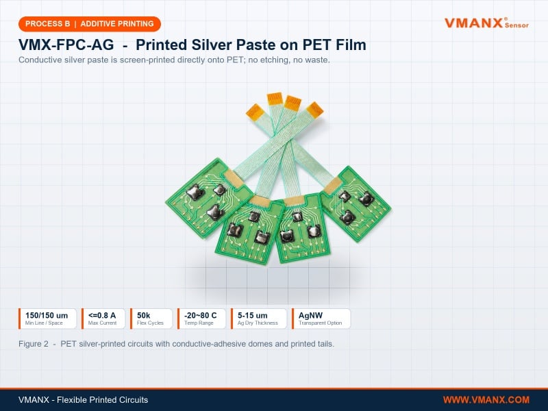
Figure 2 — PET silver-printed circuits with conductive-adhesive domes and printed tails.
Lower Cost, No Tooling Barrier
Screen printing eliminates the etching line entirely: no photo-tooling, no chemical etchant, no copper waste stream. Volume cost sits below the copper route, and because there is no etching tooling to amortise, there is no strict MOQ penalty on small batches.
Prototype turnaround is 3–5 working days against 5–7 for copper; mass production runs 7–10 days against 12–15. For a design still iterating, that difference compounds across every revision cycle.
The Transparent Capability Copper Cannot Match
PET film is optically clear, and the AgNW (silver nanowire) variant delivers 50–100 Ω/□ sheet resistance at 89% or higher transmittance at 550 nm. This makes genuinely transparent circuitry possible — touch layers over displays, illuminated panels where traces must disappear, backlit graphic overlays with invisible routing.
No etched copper process can do this. Copper is opaque by nature. When a design requires the circuit to be invisible, the process route is decided before any other parameter is discussed.
Where the Limits Sit
Honesty about constraints prevents field failures. PET has a low glass transition temperature and is not solderable — reflow will deform the substrate. Components mount only through low-temperature conductive adhesive, which suits metal domes and simple contacts but is not a production-speed path for dense component fields.
Current capacity is limited to roughly 0.8 A with 10 μm silver on a 1.0 mm trace, thermally bounded. The service window is -20 °C to +80 °C, minimum line and space is 150/150 μm (100/100 μm with advanced process), flex life is around 50,000 cycles, and impedance control is not recommended.
Side-by-Side Comparison
| Parameter | VMX-FPC-CU (PI Copper) | VMX-FPC-AG (PET Silver) |
| Substrate | PI, 12.5 / 25 / 50 / 125 μm | PET, 50 / 75 / 100 / 188 / 250 μm |
| Conductor | RA / ED copper, 18 / 35 / 70 μm | Printed silver paste, 5–15 μm dry |
| Process | Subtractive etching | Additive screen printing |
| Protection | PI coverlay, 12.5–25 μm | UV dielectric ink / low-temp PI |
| Surface Finish | ENIG, OSP, Immersion Tin | Not applicable |
| Min Line / Space | 75/75 μm (50/50 μm at 0.5 oz) | 150/150 μm (100/100 μm advanced) |
| SMT Reflow | Supported | Not supported |
| Component Mounting | Soldering | Conductive adhesive only |
| Max Current | 2 A (1 oz Cu) | ≤0.8 A |
| Insulation Resistance | ≥100 MΩ @ 500 VDC | ≥10 MΩ @ 500 VDC |
| Impedance Control | 50 Ω / 100 Ω, ±10% | Not recommended |
| Flex Life | >200,000 cycles | >50,000 cycles |
| Bend Radius (dynamic) | ≥6× total thickness | ≥12× total thickness |
| Temperature Range | -40 °C to +150 °C | -20 °C to +80 °C |
| Solder Resistance | 260 °C / 10 s, peak 330 °C | Non-solderable |
| Transparent Version | No | Yes (AgNW, ≥89% @550 nm) |
| Stiffener | FR-4 / PI / stainless steel | Low-temp bonded PI only |
| Prototype Lead Time | 5–7 working days | 3–5 working days |
| Mass Production | 12–15 working days | 7–10 working days |
| Volume Cost | Medium | Lower |
How to Decide in Under a Minute
Four questions resolve almost every case:
1. Does the design need SMT reflow soldering? If yes, the decision is made — PI copper. PET cannot survive a reflow oven, and no workaround changes that.
2. Must any part of the circuit be transparent? If yes, the decision is made in the other direction — PET silver with AgNW. Copper is opaque.
3. Does operating temperature exceed +80 °C or fall below -20 °C? Outside that window, only PI copper qualifies.
4. Does any conductor carry more than 0.8 A, or require controlled impedance? Both point to PI copper.
If none of the four apply — a low-current signal circuit, 1–2 layers, few or no soldered components, benign temperature — then PET silver delivers the same function at lower cost and faster turnaround. Choosing copper in that case means paying for headroom the design will never use.
Customer FAQs
Q: Which FPC process is cheaper for volume production?
A: Printed PET silver has lower volume cost. It eliminates photo-tooling, etchant chemistry and copper waste, and carries no strict MOQ penalty because there is no etching tooling to amortise. The saving is real only when the design fits within PET's limits: ≤0.8 A current, -20 °C to +80 °C, no reflow soldering.
Q: Can I mount SMD components on a PET silver FPC?
A: Not by reflow soldering. PET has a low glass transition temperature and deforms in a reflow oven. Components attach only through low-temperature conductive adhesive, which works well for metal snap domes and simple contacts but is not a production-speed path for dense component fields. Any design with significant SMT content should use PI copper.
Q: Why does PI copper last four times longer in bending?
A: Rolled-annealed copper has an elongated grain structure aligned with the rolling direction, which resists crack propagation under repeated flexure. Printed silver is a particle-and-binder composite; repeated bending gradually breaks particle-to-particle contact and raises resistance. This gives 200,000 cycles against 50,000 at MIT R0.8 mm.
Q: Is a transparent flexible circuit really possible?
A: Yes, on the PET route using an AgNW layer that reaches 50–100 Ω/□ sheet resistance at 89% or higher transmittance at 550 nm. It suits transparent touch layers, illuminated panels and display overlays. Etched copper cannot be made transparent at any thickness.
Q: What lead time should I plan for?
A: PET silver prototypes take 3–5 working days and mass production 7–10. PI copper prototypes take 5–7 working days and mass production 12–15, reflecting the additional drilling, plating, etching and surface-finish steps.
Q: Can both processes be used in one product?
A: Yes, and hybrid designs are common. A dense controller board uses PI copper for the SMT-populated section while a PET silver circuit handles the low-current keypad or transparent touch layer, joined by a connector. VMANX runs both process lines in-house, so a single supplier can quote and build the complete interconnect set.
Q: What quality system covers these products?
A: Both series are produced under ISO 9001 quality management with RoHS and REACH substance compliance, referencing IPC-6013 class requirements for flexible printed circuitry. Every batch passes electrical test before packaging.
DFM Review and Engineering Support
Selecting a process route early avoids expensive redesign after tooling. VMANX engineering reviews schematics against both routes and returns a DFM report covering trace width and current capacity, bend radius against installation geometry, component mounting method and stiffener strategy. Full datasheets are published on the industrial FPC printed circuit sensor page, with the broader flexible printed circuits range and related HMI human machine interface and membrane switch products covering complete interface assemblies.
Conclusion
There is no better process route — only a correct one for each design. Etched PI copper buys precision, reflow compatibility, current capacity and temperature range. Printed PET silver buys lower cost, faster turnaround and optical transparency. Establishing which four constraints apply before layout begins is what separates a clean production release from a redesign after first article.
Media & SEO Suggestions
Hero image: filename: pi-copper-vs-pet-silver-fpc-comparison.jpg | ALT: “Side-by-side comparison of amber PI copper etched FPC and green PET printed silver flexible circuits with process specifications”
Figure 1: filename: etched-pi-copper-fpc-smt-assembly.jpg | ALT: “Amber polyimide copper FPC assemblies with soldered metal snap domes and gold-plated contact tails”
Figure 2: filename: printed-pet-silver-fpc-flexible-circuit.jpg | ALT: “Green PET flexible circuits with screen-printed silver paste traces and conductive adhesive mounted snap domes”
Video (YouTube): “PI Copper vs PET Silver FPC — Flexible Circuit Process Selection Guide | VMANX”
Primary keyword: PI copper vs PET silver FPC
Secondary keywords: flexible printed circuit process comparison, etched copper foil FPC, printed silver paste circuit, transparent flexible circuit AgNW, FPC selection guide, SMT reflow flexible circuit
Meta description (156 characters): “PI copper vs PET silver FPC compared: etched copper foil supports SMT reflow, 2 A and -40 to 150 C; printed silver offers lower cost and transparent AgNW options.”
Certification scope (F4 industrial family): ISO 9001 · RoHS · REACH · IPC-6013 reference
Publishing note: display the publish date on the news homepage; maintain a 2–4 articles per month cadence.