EN
EN

Capacitive Sensing Film Sensor — Rework Cut Risk Assessment
| Item | Details | Item | Details |
| Case No. | VMANX-8D-2026-008 | Document Version | A0 |
| Product | Capacitive Sensing Film Sensor (FPC type) | Reference Code | CS-2026-008 (neutralized) |
| Customer | European medical device OEM (identity protected) | Date | Aug 2026 |
| Prepared by | VMANX Engineering / Quality Assessment Center | Classification | Confidential — Case Study |
Note: Client part numbers and product codes have been neutralized to protect confidentiality.
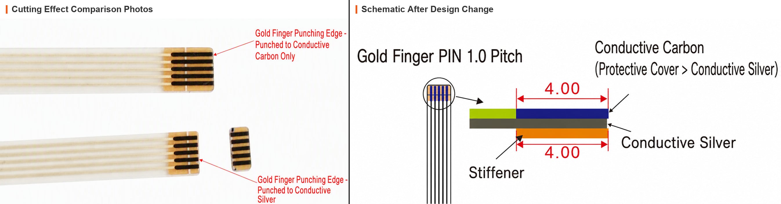
EXECUTIVE SUMMARY
A medical device OEM faced a design change on 2,000 finished capacitive sensing film sensors: the FPC stiffener was to be shortened from 7.00mm to 4.00mm to resolve an assembly clearance issue, and manual rework cutting of the finger area was proposed for the existing stock.
VMANX engineering evaluated the rework approach and strongly recommends Option B (new production) instead of Option A (rework cutting). Although rework appears cheaper on the surface, the cut line at 4.00mm crosses the silver trace end-face, exposing bare silver and triggering irreversible electrochemical migration (ECM) failure — a latent defect that may surface months later as intermittent shorts at the customer site.
D0 — PROBLEM DESCRIPTION
| Item | Description |
| What | 2,000 pcs finished sensors: stiffener length change from 7.00mm to 4.00mm required for assembly clearance |
| When | During assembly integration at the customer's site |
| Where | FPC finger (connector tail) area of the capacitive sensing film sensor |
| Who | OEM customer requesting disposition of existing finished goods |
| Why | Manual cutting is a destructive secondary process; it damages the carbon protection layer and exposes the silver layer — risk assessment required before disposition |
| How | Option A: rework cutting (risk uncontrollable) vs Option B: new production batch (4.00mm design) |
D1 — SOLUTION DEFINITION
| Dimension | Option A — Rework Cutting | Option B — New Production |
| Process | Manual cutting of 7mm stiffener to 4mm on finished goods | New production batch with 4.00mm stiffener design |
| Quality | Destructive secondary processing, inconsistent cut quality | Full process control, consistent quality |
| Key Judgment | Cut line (4.00mm) crosses silver end-face → silver exposed | Carbon coating fully intact, no silver exposure |
| Cost | Low direct cost (labor only) | Material cost for new batch |
| Risk | Uncontrollable latent failure risk | None (new batch quality assured) |
D2 — STRUCTURE & FAILURE MECHANISM (EVIDENCE)
2.1 Actual Layer Structure (four layers, left-aligned, 0.20mm step at right)
Figure 1 shows the actual structure of the FPC finger area: Top layer — conductive carbon 6.80mm, fully covering and protecting the silver trace; Second layer — conductive silver 6.60mm, protected by carbon (0.20mm longer than silver, step at right side); Third layer — PET substrate 0.125mm, aligned with stiffener (7.00mm); Bottom layer — stiffener 7.00mm.
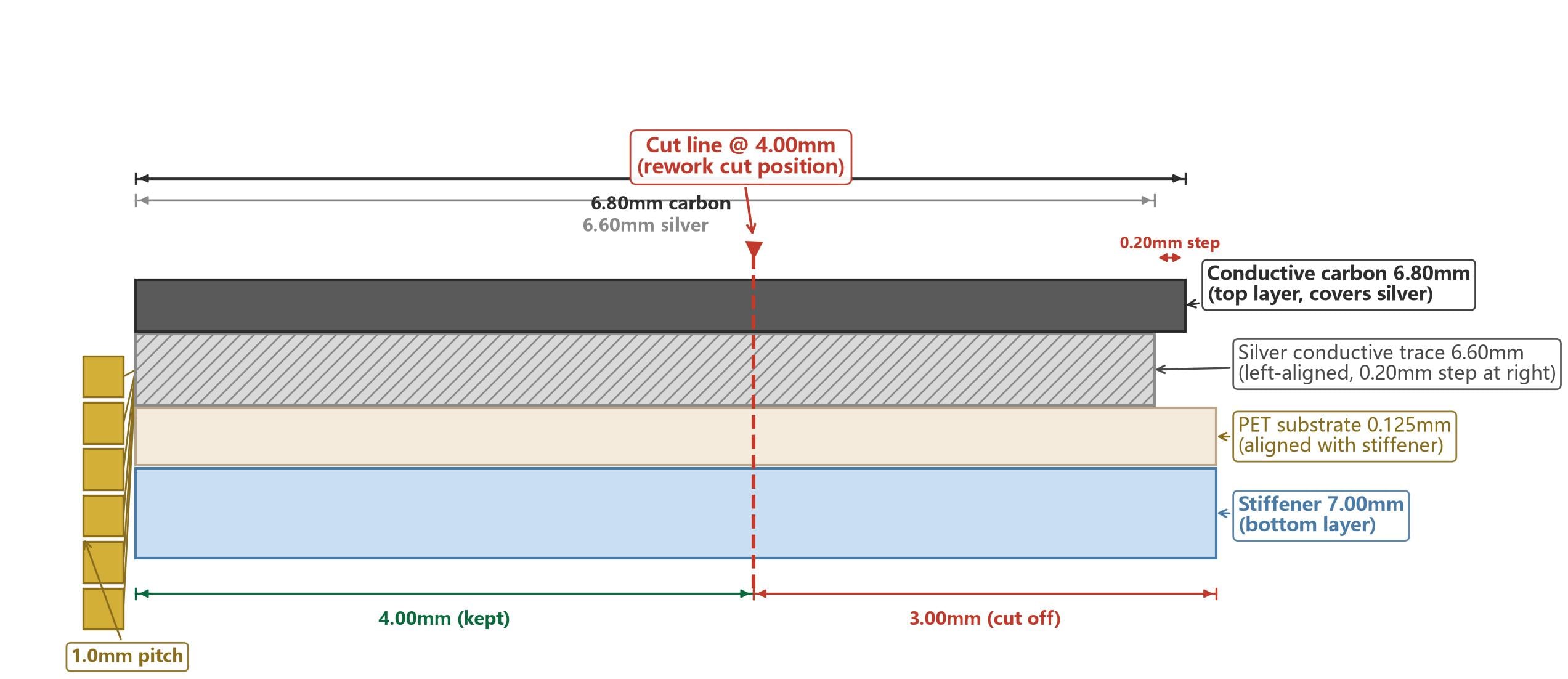
Figure 1 Four-layer structure: carbon 6.80mm / silver 6.60mm (left-aligned, 0.20mm step at right) / PET & stiffener 7.00mm; cut line @4.00mm crosses silver end-face
Rework cut position: the cut line at 4.00mm (from the contact end) lies inside the carbon (6.80mm) and silver (6.60mm) coverage zones. Cutting will sever both the carbon end-face and the silver layer end-face, leaving the silver end-face exposed without carbon protection.
2.2 Silver Migration (ECM) — the Core Irreversible Risk
Silver migration is a form of electrochemical migration (ECM). Under an electric field and moisture, silver ionizes at the anode, migrates, and reduces at the cathode forming dendrites:
• Anode: Ag → Ag⁺ + e⁻ (silver oxidizes to silver ions)
• Cathode: Ag⁺ + e⁻ → Ag (ions reduce into silver dendrites)
Acceleration factors — all present in this product: 1) Electric field: potential difference between adjacent 1.0mm-pitch fingers during operation; 2) Moisture: ambient humidity in consumer/industrial environments acts as electrolyte carrier; 3) Exposed conductor: the cut cross-section exposes silver with no moisture/oxygen barrier.
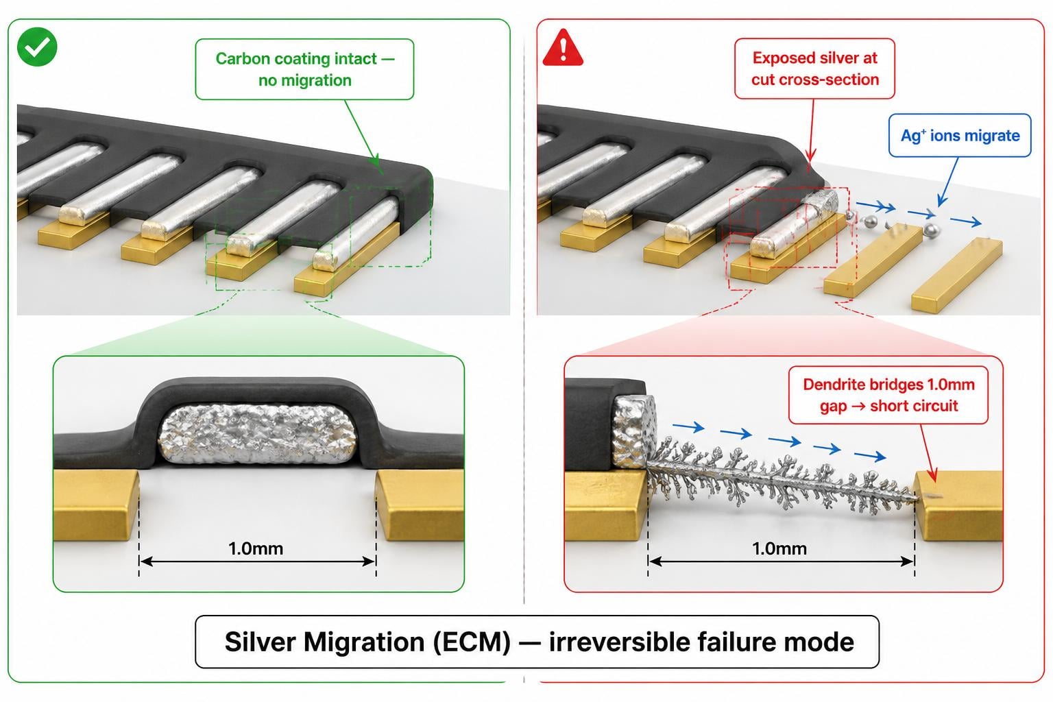
Figure 2 Silver migration mechanism: left — carbon coating intact (no migration); right — exposed silver at cut cross-section, Ag⁺ migration, dendrite bridging 1.0mm gap → short circuit
Failure timeline: with intact carbon coating, migration risk is minimal (over 5 years design life). After rework cutting, bare silver at the exposed cross-section, under 1.0mm pitch and electric field gradient, gradually grows dendrites over months or years. Once dendrites bridge adjacent pins, signal crosstalk, short circuit, or severe insulation resistance degradation occurs — random and intermittent (temperature/humidity dependent), hard to reproduce at the customer site yet real, drastically increasing after-sales failure rate.
D3 — FULL-DIMENSION COMPARISON MATRIX
| Comparison Item | Option A — Rework Cutting | Option B — New Production |
| Direct cost | Labor only (seemingly cheap) | New batch material cost |
| Physical damage risk | High — line breakage, silver peeling | None |
| Silver migration (ECM) | Extremely high — irreversible, latent | None |
| Dimensional tolerance | Very high deviation (manual cut) | Controlled by process |
| Carbon protection layer | Destroyed at cut cross-section | Intact |
| Exposed silver cross-section | Inevitable (cut crosses silver end-face) | None |
| Latent failure cost | Field shorts, recall labor, brand damage, project delay penalties — unpredictable | None (quality assured) |
| Time to delivery | Rework time + unpredictable troubleshooting | Clear, schedulable production lead time |
| Reliability basis | Undermined — destructive process vs normal process | Guaranteed — full process control |
D4 — EXPERIMENTAL DATA SUPPORT (industry reference)
| Condition | Bare silver (after cut) | Protected (carbon intact) |
| ≤1.0mm gap, 5V DC, 85% RH, 60°C | Insulation resistance drops below 10⁶Ω (failure threshold) in under 500 hours on average | Over 10¹¹Ω maintained after 2,000 hours |
| Conclusion | Exposed silver at cut cross-section = a time bomb in the circuit | Full carbon protection = design life met |
Note: Data per IPC standards and industry silver-electrode migration test references; to be jointly confirmed by both parties.
D5 — RISK SUMMARY (Option A)
| Risk Item | Level | Failure Mode | Probability |
| Silver migration (ECM) | Extremely High | Short circuit, intermittent contact failure | Medium-high (increases over time) |
| Physical circuit damage | High | Trace breakage, silver layer peeling | High (manual operation) |
| Dimensional tolerance & alignment | High | Incomplete insertion, finger deformation | Extremely high (manual cut) |
| Carbon protection layer damage | High | Silver oxidation, increased contact resistance | Extremely high |
D6 — PRECONDITIONS IF REWORK IS MANDATORY
• Pre-cut silver end-face sealing (e.g., conformal coating or edge sealant) to restore a moisture barrier — residual risk remains, must be documented and agreed
• 100% AOI + flying-probe electrical test after rework
• Environmental screening (85°C/85%RH, 500h) on a sample lot before release
• AQL 0.65 final audit and extended warranty terms agreed in writing
• Customer to sign a risk acceptance disclaimer (rework is outside normal manufacturing process)
D7 — CONCLUSION & RECOMMENDATION
VMANX strongly recommends Option B (new production). Option A appears cheaper on the surface, but the 4.00mm cut line severs the silver end-face, triggering irreversible silver migration (ECM) with unpredictable latent failure costs far exceeding the apparent savings. Quality and reliability are the foundation of long-term partnership; this design change (7mm→4mm) is a structural optimization, while physical cutting is a destructive process contrary to normal production practice.
Customer is kindly requested to weigh the decision carefully.
D8 — CONFIRMATION
| Decision | Agreed Option |
| ☐ Option A — Rework cutting (with D6 preconditions and signed risk acceptance) | |
| ☐ Option B — New production batch (recommended) |