EN
EN



Pressure Sensing That Moves Like Skin
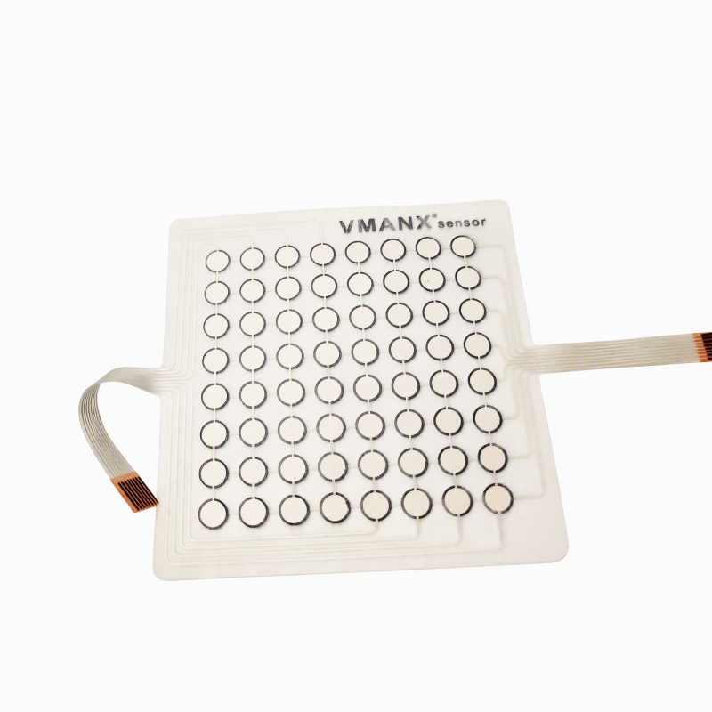
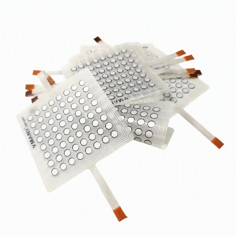
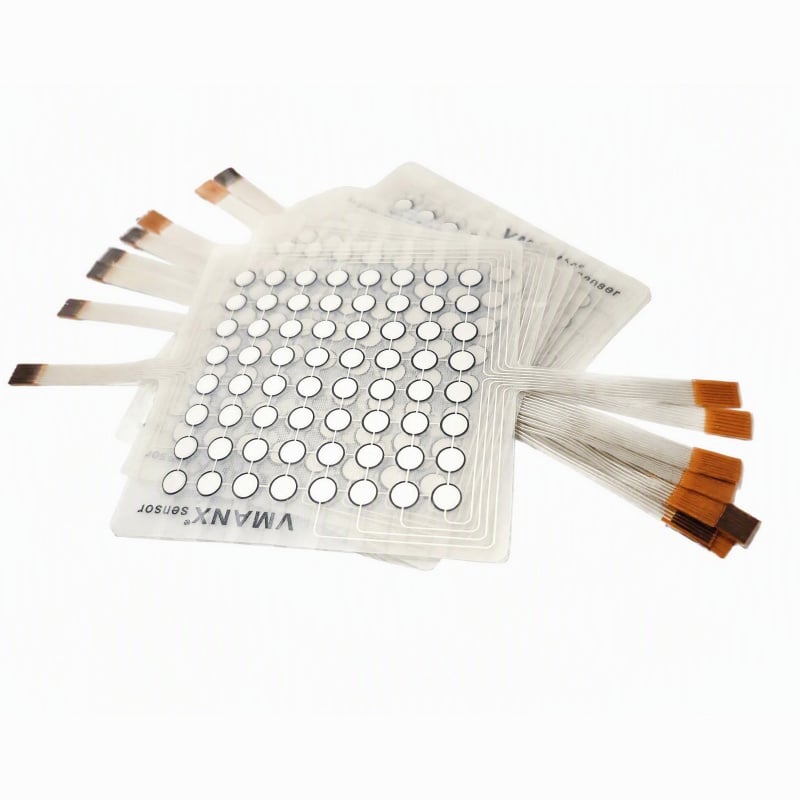
Robotic systems need more than vision. When a robot touches, grasps or interacts with a person or an object, it needs distributed contact information directly from the surface. The VMANX TPU Electronic Skin FSR Matrix converts local pressure into measurable resistance changes across an 8 × 8 sensing array, allowing the control system to reconstruct where contact occurs and how the relative force is distributed.
The sensing matrix is manufactured on a stretchable TPU substrate. Its total thickness is below 0.23 mm, giving the assembly a soft, low-profile structure that follows curved robot shells, moving joints and compliant gripper surfaces. The TPU layer can stretch and bend with the target surface, while the sensing architecture is designed to maintain pressure-sensing functionality within the qualified deformation range of each project.
This combination of mechanical compliance and distributed pressure sensing makes the sensor suitable for humanoid robot skin, dexterous manipulation, collaborative robotics and other applications where a rigid pressure board cannot follow the product geometry.
Key Performance Features
Ultra-thin construction below 0.23 mm
The complete sensing stack is less than 0.23 mm thick. The low profile helps preserve the original shape, movement and surface feel of the robot component.
Stretchable TPU substrate
TPU provides a flexible and stretchable carrier that moves with the robot surface instead of forcing the surface to remain flat.
Skin-like softness and conformability
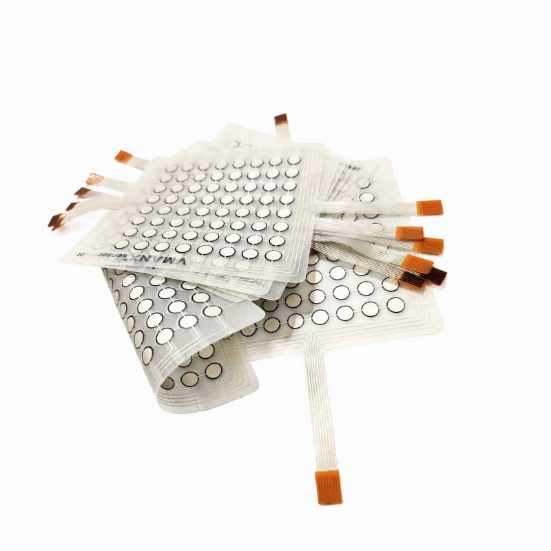
The sensor can follow flat, cylindrical and compound-curved surfaces, making it suitable for robot arms, body shells, palms and compliant end effectors.
Distributed 8 × 8 pressure matrix
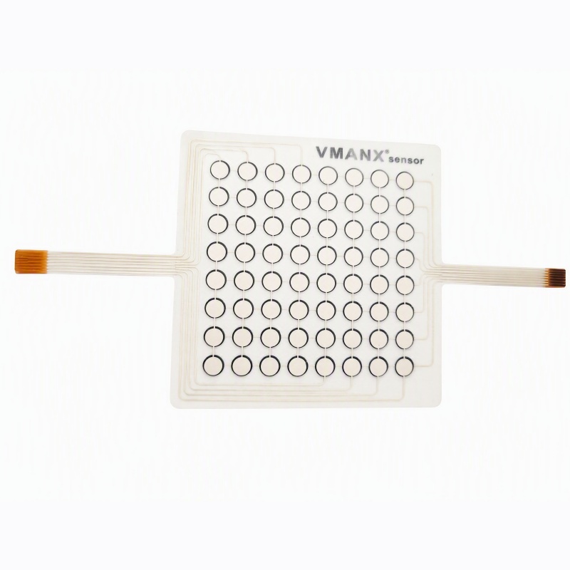
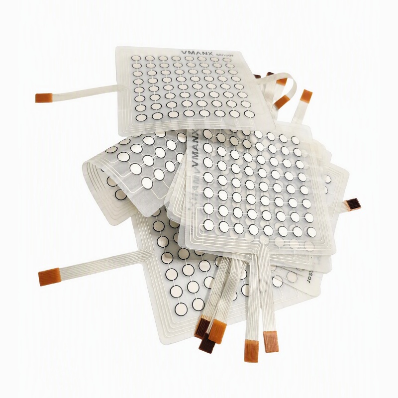
The visible standard layout contains 64 sensing points. Each node responds to local pressure so the customer electronics can build a spatial pressure map rather than receiving only a single on/off signal.
Stretch-tolerant sensing architecture
The matrix is designed to maintain pressure-sensing functionality during the intended stretch deformation. The qualified elongation limit and resistance drift must be defined by the project test report.
Transparent printed structure
The transparent or semi-transparent TPU and fine printed routing allow the matrix to integrate into light-colored robot surfaces without the visual mass of a rigid PCB.
Flexible tail routing
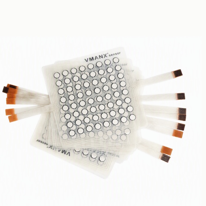
Single or multiple printed tails can be routed toward the robot wrist, joint hub, torso electronics or customer interface board.
Customizable matrix geometry
Node count, node diameter, pitch, active area, outline, tail direction and contact pitch can be adapted to the target robot surface.
Compatible with pressure mapping
Rows and columns can be scanned by customer electronics to generate relative pressure distribution, contact-location and load-balance data.
OEM-ready integration
VMANX supports matrix definition, printed electrodes, FSR layer development, TPU lamination, tail routing, sample production and project-specific validation.
How the FSR Matrix Works
1. Contact: External force deforms one or more local sensing cells.
2. Resistance change: The FSR node changes its electrical resistance in response to pressure.
3. Matrix scan: The customer circuit samples rows and columns across the 64-point array.
4. Signal conditioning: The raw resistance values are filtered, calibrated and converted by the customer electronics.
5. Pressure map: Software reconstructs contact location and relative pressure distribution.
6. Robot response: The controller can adjust grip force, stop motion, detect contact or record tactile data according to the application logic.
The scan voltage, sampling rate, conditioning circuit, calibration curve and pressure conversion algorithm are project-specific and must be matched to the final sensor configuration.