EN
EN

Designing a Flexible Seat-Cushion FSR Matrix for Stable Pressure Mapping
How a structure-first approach can reduce deformation-related signal risk while preserving routing integrity and integration flexibility.
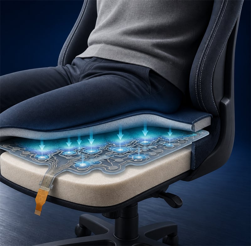
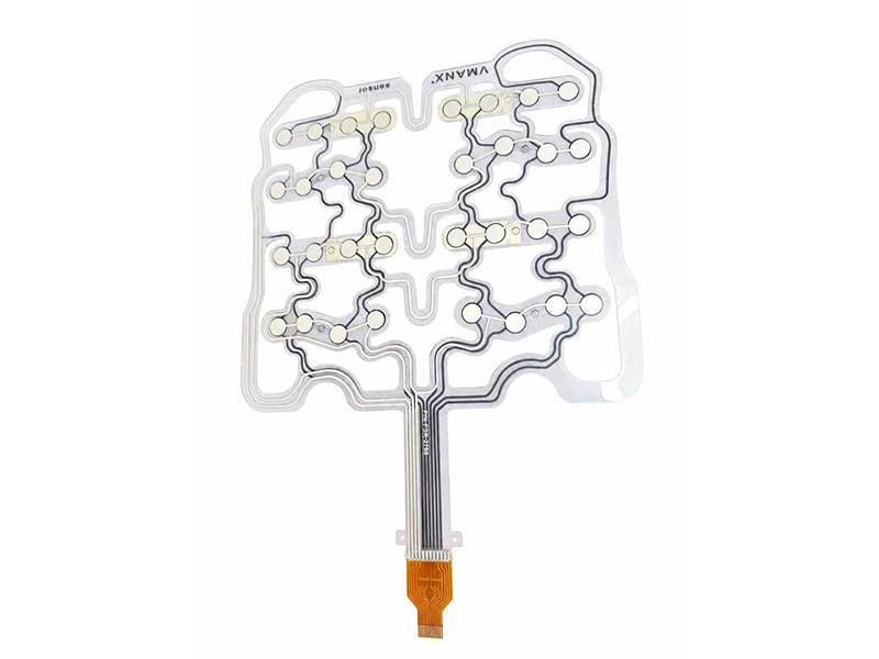
Application visualization. The sensor is integrated within a compliant cushion stack to capture distributed loading.
CASE IN BRIEF
From dense full-area geometry to a strain-releasing flexible architecture
This anonymized engineering case shows how VMANX evaluates matrix layout, mechanical deformation, flexible routing, tail transition and validation as one integrated system. No customer identity, dimensions, drawing metadata or commercial information is disclosed.
VMANX sensor
APPLICATION CONTEXT
A seat sensor must work as part of a mechanical system
A flexible seat-cushion pressure matrix may support occupancy detection, sedentary-time monitoring, posture recognition, pressure-distribution analysis and left/right or front/rear load comparison. The sensing film, however, never operates in isolation. Upholstery, foam compliance, support geometry, routing and the connector transition all influence the signal seen by the electronics.
Q. What was the core engineering question?
How can a broad sensing region remain conformable under repeated cushion deformation without allowing the film stack, conductors or tail transition to become dominant sources of unstable output?
Electrical logic
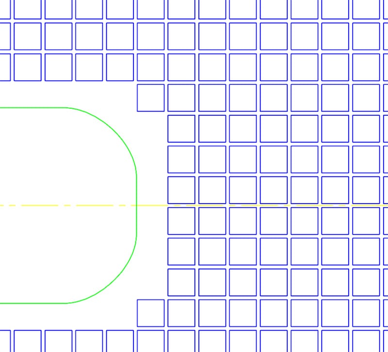
For a matrix with R rows and C columns, the theoretical intersection count is R × C, while matrix signal lines are based on R + C. Final connector pins remain subject to the controlled pinout and interface strategy.
Mechanical logic
The layout must release strain, maintain controlled spacing and keep sensitive transitions away from concentrated bending.
An anonymized local fragment used only to illustrate a dense sensing concept. Complete geometry and dimensions are intentionally withheld.
RECOMMENDED LOAD PATH
| Human load | Distributed input from the occupant |
| Upholstery / top cover | First contact and surface load spread |
| Upper comfort foam | Compliance and local pressure distribution |
| Thin-film FSR matrix | Pressure-sensing layer |
| Lower support foam | Recovery and mechanical support |
| Rigid seat support | Reaction structure |
LEARNING FROM STRUCTURAL RISK
Why can a dense full-area matrix become difficult to manage?
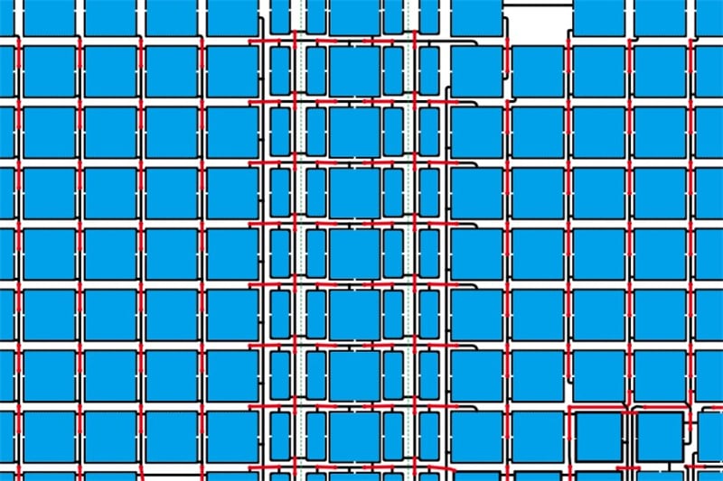
An anonymized local fragment of a dense full-area matrix architecture. No customer drawing or complete product geometry is published.
Q. What did historical experience show?
In a comparable historical design, the confirmed project outcomes included false triggering and unacceptable bendability. This evidence does not prove that every dense layout will fail; it establishes a clear reason to treat deformation behavior as a primary design input.
CONFIRMED EVIDENCE
Observed False triggering occurred in the historical comparison case.
Observed The construction did not provide acceptable bending performance.
Q. Which mechanisms should be investigated?
Potential mechanisms include local layer-gap change, unintended contact, conductor strain and stress transfer into the tail region. These are engineering hypotheses to verify through controlled prototypes and tests—not claims that every mechanism was conclusively observed in the historical sample.
GEOMETRY —— Large continuous laminate area
Global bending can be converted into local distortion.
CONDUCTORS —— Straight or constrained routing
Repeated strain may concentrate at narrow paths or transitions.
INTERFACE —— Abrupt stiffness change
Tail and connector zones require dedicated strain-relief design.
COMMUNICATION PRINCIPLE
Risk-led, not blame-led
The objective is not to label an early customer concept as “wrong.” A professional review identifies comparable evidence, explains plausible risks, proposes a manufacturable alternative and defines a validation path.
VMANX STRUCTURAL ROUTE
Release strain before asking the sensing stack to absorb it
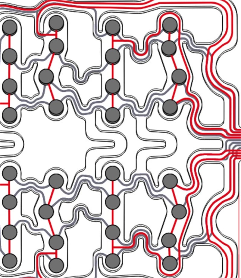
Publication-safe routing fragment illustrating cut-outs, narrow bridges and curved trace paths.
Q. How does the flexible architecture work?
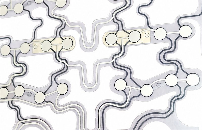
The recommended route replaces a broad continuous laminate with a geometry designed to move. Large cut-outs interrupt global stiffness, narrow bridges maintain electrical continuity, and curved or meandering conductors provide additional path length for deformation.
Large-area cut-outs
Reduce continuous laminated area and allow cushion zones to move more independently.
Narrow connecting bridges
Preserve connectivity while limiting the amount of material that carries global strain.
Curved routing
Avoids long straight paths that can pull directly against local bending.
Zoned convergence
Guides conductors toward the tail while keeping the transition outside the primary sensing region.
DESIGN INTENT
Flexibility is created by geometry—not by material choice alone
A flexible substrate does not automatically produce a flexible assembly. Pattern shape, bridge width, routing radius, layer registration, adhesive behavior and the location of stiffness transitions must be designed as one architecture.
INTERCONNECTION AND VALIDATION
Protect the transition from film body to FPC tail
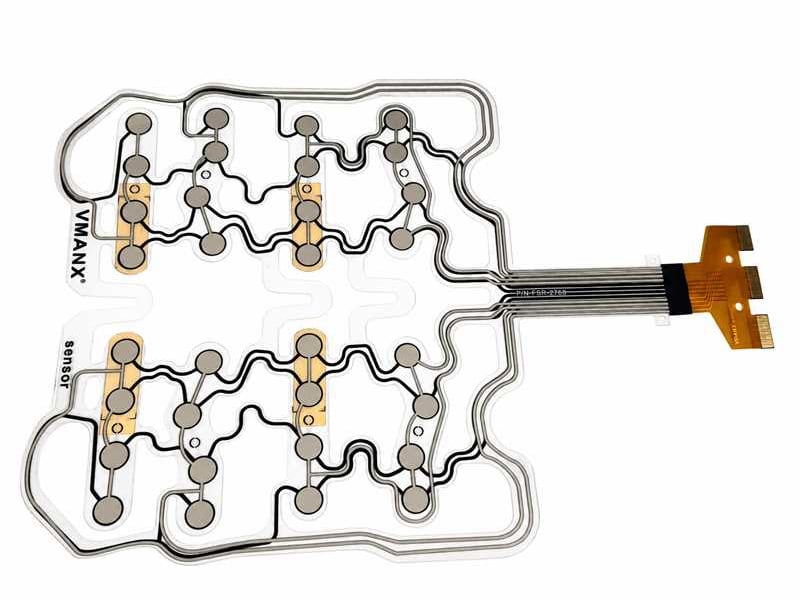
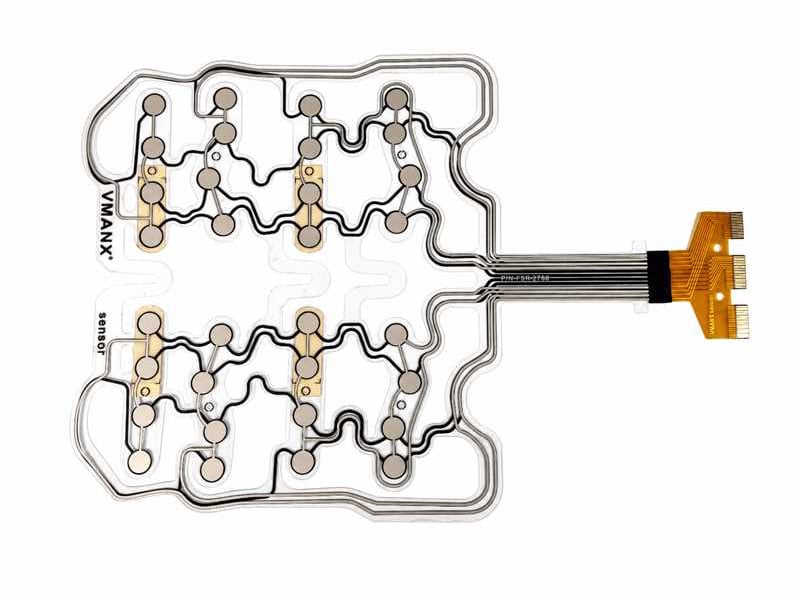
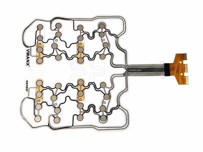
Anonymized product detail showing distributed sensing zones and curved conductors. Printed identifiers and connector markings are excluded.
Q. What matters at the tail transition?
Conductors should converge gradually within the flexible body. The transition should sit outside the primary load and frequent-bending zones, with reinforcement and a controlled stiffness gradient considered where required.
Location
Move the transition away from the highest-pressure and highest-curvature regions.
Strain relief
Use routing geometry, local reinforcement and installation control to reduce stress concentration.
Controlled definition
Freeze bend radius, terminal construction, pinout and assembly constraints during DFM and sample review.
Q. How should the concept be validated?
| Static mapping | Confirm active areas, baseline stability and spatial response under controlled loads. |
| Repeat loading | Track drift, recovery and output consistency through repeated compression. |
| Bending and flexing | Exercise representative bend zones and inspect signal stability plus conductor integrity. |
| False-trigger screening | Apply cushion deformation without intended point load and monitor unintended responses. |
| Tail robustness | Evaluate the film-to-tail transition under installation and repeated movement. |
| System calibration | Tune thresholds and algorithms with the final foam, cover and seat support. |
Acceptance limits, cycle counts and test fixtures should be agreed for the target seat construction. No unverified durability figure is presented as a completed result in this case study.
ENGINEERING OUTCOME
A manufacturable path from sensing concept to seat integration
The engineering value in this case was not a single drawing. It was the conversion of an application goal into an integrated sensing architecture that addresses mechanical compliance, electrical routing, interface protection and verification from the beginning.
WHAT THE ARCHITECTURE ENABLES
Conformable layout A geometry that can follow cushion movement.
Distributed sensing A matrix foundation for occupancy, posture and pressure mapping.
Controlled routing Signal paths designed around deformation rather than added afterward.
WHAT THE PROCESS CONTROLS
DFM review Layer stack, routing, tail position and assembly constraints.
Prototype learning Risk is reduced through evidence from representative samples.
System calibration Thresholds are tuned with the actual cushion components.
Q. When should a structure-first review begin?
Before the sensing density, outline and tail position are frozen. Early collaboration gives the mechanical and electrical architecture enough freedom to release strain, protect signal integrity and simplify later validation.
Developing a flexible pressure-sensing seat or cushion?
Share the application stack, functional goals, target sensing zones and interface constraints. VMANX can support concept review, DFM, custom matrix layout, prototype planning and validation definition.
Editorial note: This article is based on an anonymized engineering case. All customer identifiers, exact dimensions, drawing metadata, commercial terms and project-specific part references have been removed. Images are cropped illustrative fragments and do not reproduce a complete customer drawing.