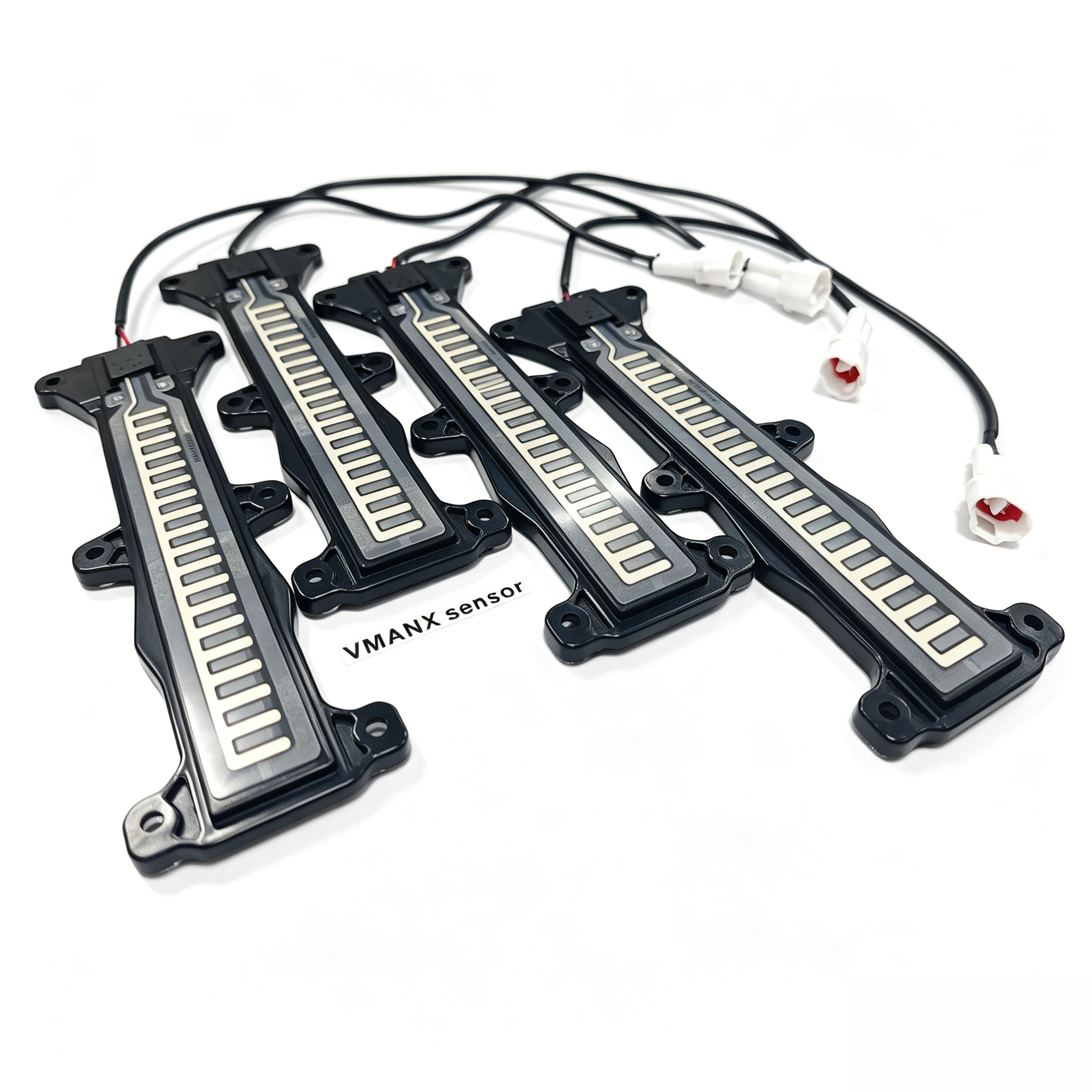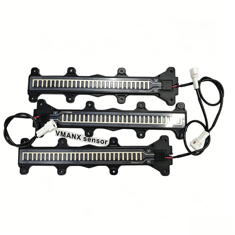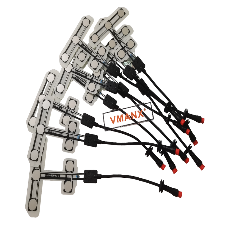
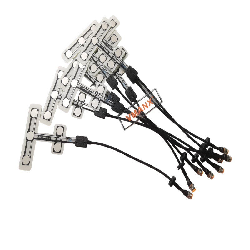
| Parameter (Unit) | Specification / Test Condition | Min | Typical | Max |
| Untriggered Resistance (MΩ) | No external force, sensor surface in a free state | 10 | — | $10^7$ |
| Trigger Threshold Resistance (kΩ) | Default reference value for trigger detection | — | 200 | — |
| Trigger Force / Sensitivity (g) | Applied pressure corresponding to initial conduction | 20 | 30–50 | 70 |
| Effective Range (g) | Linear / detectable pressure range | 20 | — | 20,000 |
| Test Voltage (V) | Recommended drive voltage for detection circuit | — | DC 3.3 | DC 5.0 |
| Operating Current (μA) | Passive component, no power supply required | — | 0 | — |
| Insulation Resistance (MΩ) | Between electrodes and the external environment | 100 | — | — |
| Activation Response Time (ms) | From force application to resistance dropping below threshold | — | <1 | 10 |
| Recovery Time (ms) | From force removal to resistance returning to high impedance | — | <15 | 20 |
Note: The resistance values listed above are recommended reference thresholds. Actual trigger resistance values can be customized according to the design requirements of the vehicle control system.
| Pressure Range (g) | Resistance Response Range (Typical) | Detection Status |
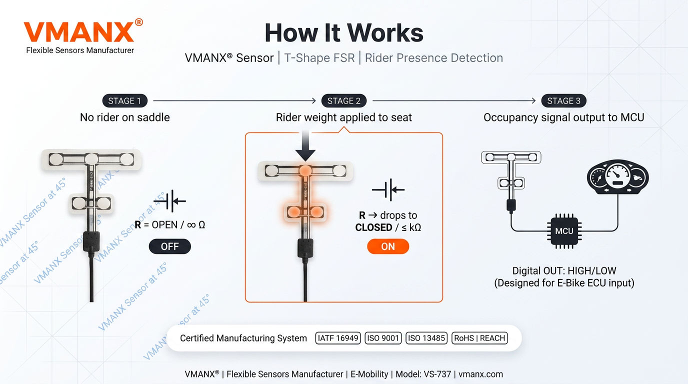
| 0 (No Load) | $>10\text{ M}\Omega$ | Unoccupied (Vacant) |
| 20 ~ 100 | 500 kΩ ~ 1 MΩ | Transition Zone |
| 100 ~ 1,000 | 200 kΩ ~ 500 kΩ | Triggered Zone |
| 1,000 ~ 6,000 | 10 kΩ ~ 200 kΩ | Stable Conduction Zone |
| >6,000 | <10 kΩ | Full Load Zone |
The pressure-resistance response exhibits a non-linear decreasing curve: the greater the pressure, the lower the resistance.
2.1 Other Performance Parameters
| Parameter | Specification / Value (Unit / Remarks) |
| Sensor Thickness | ≤0.4 mm |
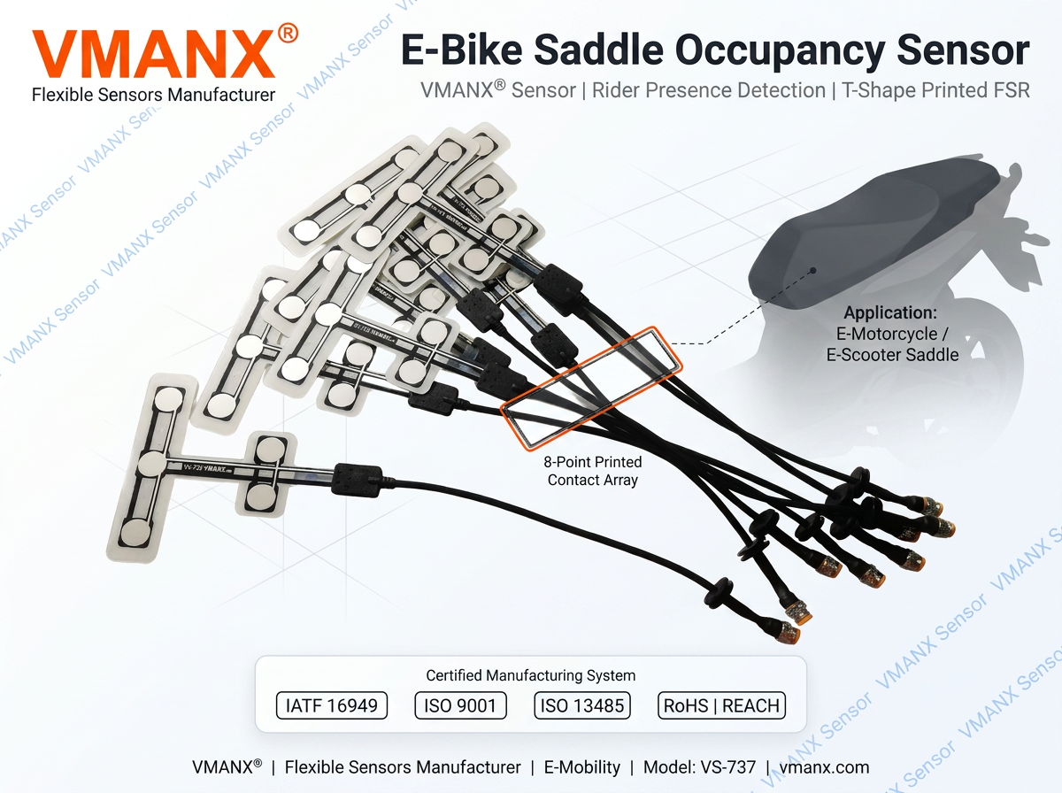
| Dimensions | Customizable (Standard Reference: L 200–350 × W 30–80 mm) |
| Output Type | Two-wire resistance output / Customizable switch level output |
| Connector Type | 2P automotive waterproof connector (SM 2.54 / Customized) |
| Encapsulation Material | Polyether-type TPU / Polyester film (PET) |
| Humidity Tolerance | 5% ~ 90% RH (Operating, non-condensing) |
| Storage Temperature | -40 ~ +85 °C |
| Operating Temperature | -40 ~ +85 °C |
All the above parameters refer to the typical specifications of current flexible thin-film pressure sensors in the automotive industry.
2.2 Sensor Port Definition & Description
| Pin Number | Signal Definition | Electrical Description |
| Pin 1 | S1 (Signal 1) | Resistance detection output (Connects to controller ADC input) |
| Pin 2 | S2 (Signal 2) | Resistance detection common terminal (Connects to controller GND) |
Notice: The sensor is a non-polar component; both ports are functionally symmetrical. It is recommended to use a pull-up fixed resistor in the vehicle-side circuit for voltage division sampling.
As an electronic component applied to road vehicles, the VMX-SSS100 is designed and validated in accordance with the environmental adaptability and durability requirements for automotive components specified in the ISO 16750 series (Road vehicles — Environmental conditions and testing for electrical and electronic equipment).
3.1 Climatic Reliability
| Test Item | Test Conditions | Reference Standard | Pass Criteria |
| High-Temperature Storage | +85°C, 1000h | ISO 16750-4 | No performance degradation, no physical deformation |
| Low-Temperature Storage | -40°C, 1000h | ISO 16750-4 | No performance degradation, no brittle cracking |
| Temperature Cycling | -40°C ~ +85°C, 50 cycles | ISO 16750-4 | Resistance response deviation ≤±10% |
| Damp Heat Test | 40°C / 93% RH, 48h | ISO 16750-4 | Insulation performance normal, no internal condensation |
| Salt Spray Test | 5% NaCl, 35°C, 48h | ISO 16750-4 | Corrosion resistant, electrical performance normal |
| Waterproof & Dustproof | IP65 rating | IEC 60529 | Waterproof and dustproof, no water ingress |
3.2 Mechanical Reliability
| Test Item | Test Conditions | Pass Criteria |
| Actuation Life (Pressing) | ≥1 million times, frequency ≤10Hz, pressure 50N | Response point shift ≤±20%, no functional failure |
| Rolling Test | Over 100,000 times, load 1500N | Structural integrity intact, function normal |
| Vibration Test | Random vibration, 10~2000Hz, acceleration 20g, 24h | No solder joint detachment, no structural loosening |
| Mechanical Shock | Half-sine pulse, peak 50g, duration 11ms | No physical damage, electrical performance normal |
| Bending Fatigue | Repeated bending radius R=20mm, ≥10,000 times | No breakage in conductive layer, resistance change ≤±5% |
| Free Drop | 1.0m height, dropped to concrete surface, 1 time per each of the 6 faces | No physical damage, function normal |
The pressing life and bending fatigue test conditions refer to domestic industry-standard testing for flexible pressure sensors. Long-term vibration adaptability complies with the environmental reliability assessment requirements for automotive electronic equipment.
3.3 Electromagnetic Compatibility (EMC)
| Test Item | Characteristic Description |
| Electromagnetic Interference (EMI) | The sensor is a passive device and generates no electromagnetic emissions during operation. |
| Electrostatic Discharge (ESD) | The device structure is insensitive to electrostatic discharge; no extra protection is required under normal installation environments. |
| Electromagnetic Susceptibility (EMS) | The resistance signal output characteristic is immune to electromagnetic interference, requiring no additional shielding. |
The sensor is a passive resistive component with excellent EMC characteristics. It will not introduce any additional interference sources when the vehicle system undergoes EMC certification.
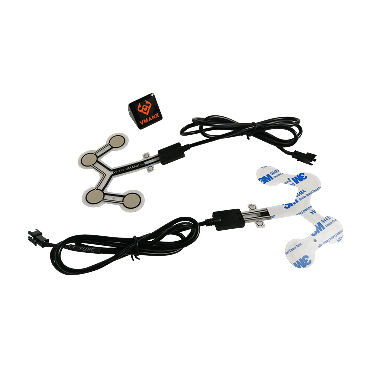
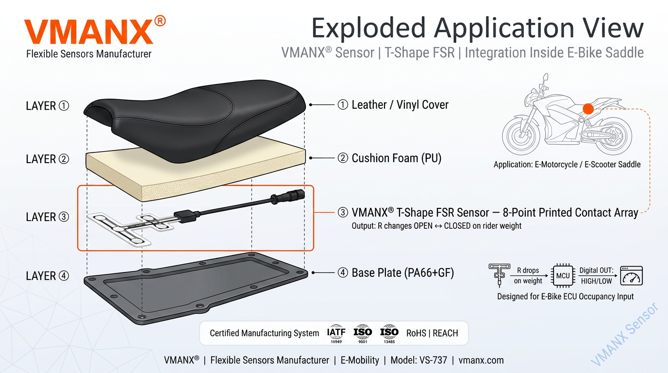
| Substrate: | High-toughness polyester film (PET) |
| Functional Layer: | Precision-printed conductive electrodes + nano-piezoresistive functional materials |
| Encapsulation: | Polyether-type TPU full sealing or PET film lamination encapsulation |
| Total Thickness: | ≤0.4mm |
| Customizable Items: | Outline dimensions, sensing area layout, pressure range, trigger threshold resistance values. |

Dongguan Zhongman Industrial Co., Ltd.
 EN
EN