EN
EN

8D Corrective Action Report — Membrane Switch Key Failure
| Item | Content | Item | Content |
| Report No. | 8D-20260902-001 | Part No. | Vmanx.1916 |
| Revision / Status | V1.0 / Issued for customer review | Confidentiality | Controlled (bilateral communication) |
| Issue Date | 02 September 2026 | Lot / Batch | 24-09-03 |
| Prepared by | Engineering Dept. / Quality Assessment Center | Production Date | 03 September 2024 |
| Customer | [European Customer] | Product | Membrane Switch, 6-layer construction |
| Failure Mode | Inverted metal snap dome (snap-through) | Scope | D0 – D8, full discipline coverage |
Decision Summary (Conclusion First)
The metal snap domes in the returned samples have inverted (snapped through): the pre-formed convex disc has buckled permanently into the concave direction and now rests against the printed contact pad. This single physical condition produces all three reported symptoms simultaneously — loss of tactile feedback, reduced travel, and a permanently closed (stuck-on) circuit.
Assessment conclusion: dome inversion is an irreversible mechanical over-stress event, not a wear-out or ageing mode. Lot 24-09-03 passed a 100% tactile and electrical continuity test before shipment, which an inverted dome cannot pass by definition; the over-stress was therefore introduced after outgoing inspection — during transport, storage, handling or assembly. VMANX accepts the systemic gap identified in Why 4: the handling requirements of the snap dome were not sufficiently communicated with the product. Sections D5 and D7 close that gap from both directions.
D0 Preparation and Emergency Response
| Element | Description |
| Reported symptom 1 | No tactile feedback when the key is actuated — the characteristic "click" is absent. |
| Reported symptom 2 | Continuous / permanent electrical response — the key behaves as if held down (stuck-on, always closed). |
| Reported symptom 3 | Reduced key travel compared with a conforming unit. |
| Emergency action 1 | Customer notified to stop using lot 24-09-03 immediately. Executed. |
| Emergency action 2 | In-transit goods and customer-side inventory placed under quarantine. Executed. |
| Emergency action 3 | Full lot traceability and internal investigation initiated. Executed. |
D1 Cross-Functional Team
| Role | Function | Responsibility |
| Team Leader | Quality Engineering | Overall coordination, root cause ownership, 8D authoring |
| Member | Engineering | Failure mechanism analysis and design countermeasures |
| Member | Production | Process traceability and in-process verification |
| Member | Quality Control | Inspection execution and data confirmation |
| Member | Customer Service | Customer communication and field information collection |
D2 Problem Description (5W2H)
| Element | Description |
| What | Membrane switch key failure. The metal snap dome has inverted (snap-through): the domed centre is permanently buckled downward and the convex arch structure is lost. |
| When | Reported 02 September 2026. Affected units manufactured 03 September 2024 (lot 24-09-03). |
| Where | Customer end-product assembly line and field use sites. |
| Who | Detected and reported by the customer quality department. |
| Why (effect) | Inversion produces three coupled effects: travel is shortened; the return force is lost, so there is no tactile feedback; the dome centre stays in contact with the circuit layer, forming a permanently closed circuit. |
| How detected | The customer delaminated the switch layers and visually confirmed the inverted metal dome. |
| How many | Pending customer data — defective quantity and defect rate required (see D8). |
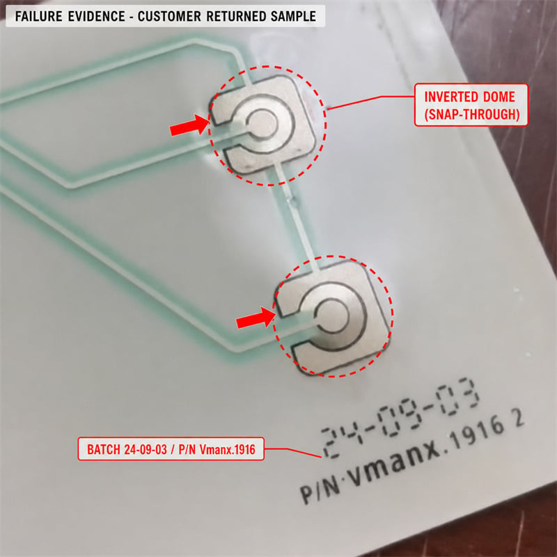
Returned sample, lot 24-09-03 / P/N Vmanx.1916 — both metal snap domes inverted; red arrows mark the affected domes.
The red arrows and dashed circles mark the two metal snap domes on the circuit layer of the returned sample. Both show the inverted condition: the dome centre is buckled into the concave direction and sits permanently against the printed contact pad, which is why the key reads as continuously closed. The lot marking 24-09-03 / P/N Vmanx.1916 at the lower right confirms sample traceability to the reported batch.
D3 Interim Containment Actions
| # | Containment Action | Owner | Status |
| 1 | Customer instructed to quarantine all remaining stock of the affected lot | CS / Quality | Done |
| 2 | In-transit goods intercepted and subjected to 100% inspection | Quality | Done |
| 3 | Remaining warehouse stock of the lot segregated and blocked | Warehouse | Done |
| 4 | Replacement lot supplied to protect the customer production schedule | Production | Ongoing |
| 5 | Customer supported in screening and replacing units already assembled | CS / Engineering | Ongoing |
D4 Structure and Failure Mechanism Evidence
The product is a six-layer membrane switch. The metal snap dome is retained in a pocket formed by the double-sided spacer (layer 4) and acts against the printed contacts of the circuit layer (layer 5). The backing plate supplied by the customer forms the load-bearing surface beneath layer 6 and is the element that physically limits dome travel.
| Layer | Description | Function |
| 1 | Graphic overlay, PET 0.15 mm | User interface, printed graphics, environmental seal |
| 2 | Overlay adhesive, 0.05 mm | Bonds the overlay to the layers below |
| 3 | Spacer / fixing layer, PET 0.05 mm | Retains and locates the dome |
| 4 | Double-sided spacer adhesive | Forms the dome pocket and the open-circuit air gap |
| 5 | Circuit layer, PET 0.15 mm (silver / carbon / dielectric) | Printed conductive traces and contact pads |
| 6 | Rear mounting adhesive | Bonds the switch to the customer backing plate |
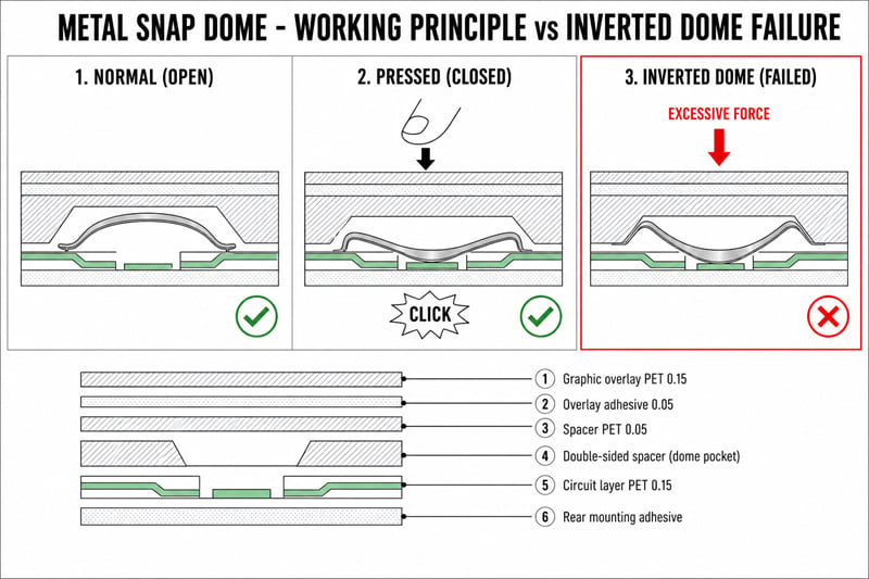
Metal snap dome — normal (open), pressed (closed) and inverted (failed), with the six-layer construction.
Normal operation. The metal snap dome is a pre-formed convex disc. Actuation causes a controlled elastic buckling event that generates the tactile "click" and bridges the two printed contacts. On release, the stored elastic energy returns the dome to its convex state and the circuit opens. The transition ring at the dome apex is the geometric datum from which the dome radius is developed; any damage to this ring degrades or destroys the return behaviour.
Inverted dome (snap-through). When the applied force drives the dome beyond its designed maximum travel, the arch buckles past its elastic limit into a second stable position. The dome becomes bi-stable: it no longer returns to the convex state but remains concave, with its centre held against the circuit layer. The consequence is simultaneous loss of tactile feedback, reduced travel and a permanently closed contact — precisely the symptom set reported by the customer.
Critical characteristic: dome inversion is a mechanical over-stress event, not a gradual wear-out or ageing mode. It occurs instantaneously under a single over-travel actuation, impact, bending action or sustained compressive load, and it is irreversible. An inverted dome cannot be recovered by any field action and the affected switch must be replaced.
D4.1 Five-Why Analysis
| Level | Question | Answer |
| Why 1 | Why did the dome invert? | It received an actuation force exceeding its designed maximum travel. |
| Why 2 | Why was it subjected to over-travel force? | The dome lacked adequate rigid backing support while being pressed, so nothing physically limited the deflection at the travel limit. |
| Why 3 | Why was rigid support absent? | During customer-side assembly, handling, transport or storage the support condition beneath the dome did not meet the design requirement — actuation on a non-flat surface, an unsupported gap under the key area, accidental impact, or a sustained compressive load. |
| Why 4 | Why did that condition occur? | Metal snap domes are highly sensitive to the support and loading environment: they must be handled flat on a rigid surface, any bending, back-flexing or impact destroys the mechanical balance, and once over-deflected the dome does not recover. This sensitivity and the resulting handling requirements were not sufficiently communicated in the documentation delivered with the product. |
| Why 5ROOT CAUSE | What is the underlying root cause? | The switch was subjected to mechanical stress beyond the design specification — over-travel actuation, impact, bending or sustained load — during customer-side assembly, handling, transport or storage. This destroyed the dome transition ring and buckled the arch into an irreversible inverted state. The contributing systemic gap on the supplier side is the absence of an explicit, illustrated handling specification delivered with the product. |
D4.2 Cause and Effect Analysis (4M1E)
| Category | Potential Cause | Assessment |
| Man | Actuation or handling on a non-flat surface; panel bent during rework or pick-up | CONTRIBUTING |
| Machine | No rigid backing plate beneath the key area; unsupported gap under the dome pocket | CONTRIBUTING |
| Material | Incoming dome actuation force, return force and travel verified against specification | EXCLUDED |
| Method | No handling specification issued to the customer; no operator training mechanism in place | CONTRIBUTING |
| Environment | Sustained load in transit; flat-stacked packing; impact during handling and storage | CONTRIBUTING |
| Supplier process | Dome placement, lamination and outgoing test at the VMANX facility | EXCLUDED |
D4.3 Verification of the VMANX Manufacturing Process
| # | Verification Performed | Result |
| 1 | Incoming inspection of the dome lot: actuation force, return force and travel | All parameters within specification |
| 2 | In-process control: dome placement on flat rigid worktables under a defined platform requirement | Compliant, no deviation recorded |
| 3 | Outgoing inspection: 100% electrical continuity test and 100% tactile check | 100% pass, zero rejects |
| 4 | Historical data review across other lots of the same product family | No systematic dome inversion observed |
Traceability conclusion: the failure did not originate in the VMANX manufacturing process. Every unit of lot 24-09-03 passed a 100% tactile and continuity test before shipment. An already-inverted dome forms a permanently closed circuit, which the outgoing continuity test detects and rejects by definition — such a unit cannot pass and cannot be shipped. The inversion therefore occurred after outgoing inspection.
Positioning statement: the purpose of this section is factual boundary-setting, not attribution of blame. Irrespective of where the mechanical stress was applied, VMANX accepts responsibility for the systemic gap identified in Why 4 and is committed to supporting the customer in eliminating the field conditions that allow over-stress to occur.
D5 Permanent Corrective Actions
| # | Corrective Action | Owner | Due |
| 1 | Add a prominent warning card to every package: "Metal snap dome — handle flat on a rigid support. Do not bend, back-flex, impact or compress." | Engineering / Quality | Immediate |
| 2 | Update the product specification and instruction sheet with a dedicated illustrated chapter on metal snap dome handling | Engineering | Within 1 week |
| 3 | Upgrade packaging: foam cushioning top and bottom, panels packed upright on edge instead of flat-stacked to eliminate sustained key compression | Production / Engineering | Within 2 weeks |
| 4 | Offer a design option: rigid protective cover plate or local stiffener above the dome area for demanding assembly environments | R&D | Within 1 month |
| 5 | Provide an assembly training video demonstrating correct dome handling, mounting and liner removal | Customer Service / Engineering | Within 1 week |
D5.1 Handling Standard — Correct versus Prohibited Practice
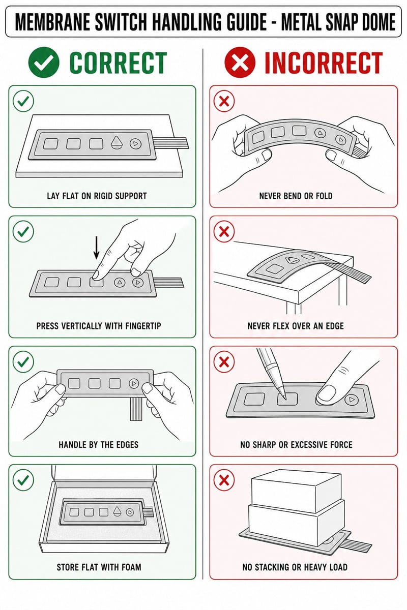
Membrane switch handling guide for metal snap dome products — correct practice versus prohibited practice.
| Correct Practice | Prohibited Practice |
| Lay the switch flat on a rigid support before any actuation. | Never bend or fold the panel. |
| Press vertically with the fingertip pad, using normal actuation force only. | Never flex the panel over a table edge or corner. |
| Handle the panel by its outer edges, never by the key area. | Never use sharp objects or excessive force (pen tip, fingernail, tool). |
| Store flat with foam protection over the key area. | Never stack items or apply a heavy load onto the key area. |
D5.2 Assembly, Packaging and Storage Standard
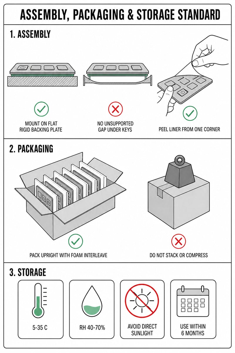
Assembly, packaging and storage work standard for metal snap dome membrane switches.
| Stage | Mandatory Requirement |
| Assembly | Mount the switch onto a flat, rigid backing plate. This is the single most important control: the backing plate is the physical element that limits dome travel and prevents snap-through. |
| Assembly | No unsupported gap may exist beneath any key area. A flexible, thin or hollow housing under the dome permits over-travel and will eventually invert the dome. |
| Assembly | Peel the release liner from one corner at a shallow angle. Never pull the liner across the key area and never fold the panel back on itself during liner removal. |
| Packaging | Pack panels upright on edge with foam interleaving between units. |
| Packaging | Do not stack or compress. A sustained load on the key area over several days of transit is sufficient to invert a dome even without impact. |
| Storage | Temperature 5 – 35 °C; relative humidity RH 40 – 70 %; avoid direct sunlight; use within 6 months of delivery. |
D5.3 Risk Notice — Consequences of Non-Compliance
| Improper Action | Resulting Failure | Recoverable |
| Actuation without rigid backing | Dome over-travel, inversion, permanently stuck-on key | NO |
| Bending or back-flexing the panel | Transition ring deformed, loss of return force and tactile feel | NO |
| Sharp object or excessive force | Dome deformation, overlay puncture, contact damage | NO |
| Flat-stacking under sustained load | Progressive compression leading to dome inversion | NO |
| Creasing the circuit layer | Micro-cracking of the printed silver trace, open circuit | NO |
D6 Implementation and Verification
| Action | Status | Verification Method | Result |
| Warning card added to packaging | Complete | Packaging document review | Packaging BOM updated |
| Specification and instruction sheet update | Ongoing | Customer review and confirmation | Awaiting customer feedback |
| Packaging upgrade | Ongoing | Drop test and stacking / compression test | Test report pending |
| Assembly training video | Ongoing | Customer training confirmation | Delivery pending |
| Rigid cover design option | Ongoing | Sample build and functional test | Sample evaluation pending |
D6.1 Preconditions for Continued Use of the Affected Lot
Should the customer wish to release any quarantined material rather than replace it, the following engineering preconditions must be satisfied in full:
① Engineering change review and written customer confirmation of the screening method, acceptance criteria and responsibility boundary.
② First-article verification: 100% tactile check on a rigid reference fixture, confirming full dome return and no reduced travel.
③ Electrical verification: continuity test in the released state, confirming no permanently closed contact on any key.
④ 100% inspection before release, with a bilateral retained sample confirmed by both parties.
Residual risk statement: a dome that has been partially over-deflected but not yet fully inverted cannot be reliably detected by tactile or continuity testing. Screened material therefore carries a residual field-failure risk that cannot be fully eliminated, and its acceptance requires written confirmation by both parties.
Ongoing verification plan: the next three consecutive production lots will undergo 100% tactile and electrical continuity inspection with a target defect rate of zero. The inspection record will be issued to the customer with each shipment.
D7 Prevention of Recurrence
| Scope | Preventive Measure |
| Horizontal deployment | Review all products containing metal snap domes and roll out the unified warning card and handling instruction to every affected part number. |
| FMEA | Add the failure mode "Metal snap dome inversion (snap-through)" to the FMEA database with its detection and prevention controls and a revised RPN. |
| Control Plan | Update the Control Plan to include a mandatory customer-notification requirement for handling specifications at first article and at every packaging change. |
| Supplier management | Align incoming inspection criteria with the dome supplier and add force-travel curve testing, so that dome stiffness and travel limit are characterised rather than only pass / fail checked. |
| Design phase | Evaluate, for every new product, whether a rigid backing plate or a dome protection structure is required, and record the decision in the design review. |
| Customer communication | Establish periodic handling-standard training and follow-up visits, so that assembly conditions at the customer site are verified rather than assumed. |
The essence of this issue is a mismatch between an intrinsic product characteristic — the high mechanical sensitivity of the metal snap dome — and the actual field condition, namely the absence of a defined rigid support. The corrective strategy therefore does not seek to allocate blame. It closes the mismatch from two directions simultaneously: improved information transfer through the warning card, the illustrated specification and the training video, and physical protection through upgraded packaging and an optional rigid cover design. Both directions are required; either one alone leaves residual risk.
D8 Conclusion, Recognition and Bilateral Confirmation
Recommended action: replace the affected units rather than screen and release them. Dome inversion is irreversible and partially over-deflected domes are not reliably detectable, so replacement is the only route that restores full field reliability. The corrective actions in D5 eliminate the recurrence path for all future lots.
One-sentence conclusion: an inverted snap dome is a permanently closed switch inside the customer product — reliability is not restored by inspection, it is restored by removing the over-stress condition and replacing the affected parts. Quality and reliability are the foundation of a long-term partnership.
Information Requested from the Customer
| # | Requested Information | Purpose |
| 1 | Defective quantity and defect rate for the affected lot | Completes the "How many" field in D2 and sizes the containment |
| 2 | Photographs or physical samples of further failed units | Confirms whether all failures share the same inversion signature |
| 3 | Description of the assembly fixture and the backing support beneath the switch | Key evidence — verifies whether an unsupported gap exists under the key area |
| 4 | Transport and storage conditions applied to the lot | Assesses sustained-load and impact exposure during logistics |
| Item | Customer Confirmation | VMANX Confirmation |
| Root cause accepted | □ Accepted □ Not accepted | □ Confirmed |
| Disposition of affected lot | □ Replacement □ Screening per D6 | □ Agreed □ Not agreed |
| D5 corrective actions accepted | □ Accepted □ Further action required | □ Confirmed |
| Signature / Date |
This report is issued by the VMANX Engineering Department / Quality Assessment Center, which retains the right of interpretation. It constitutes a technical assessment and does not by itself approve or release any disposition of the affected material.