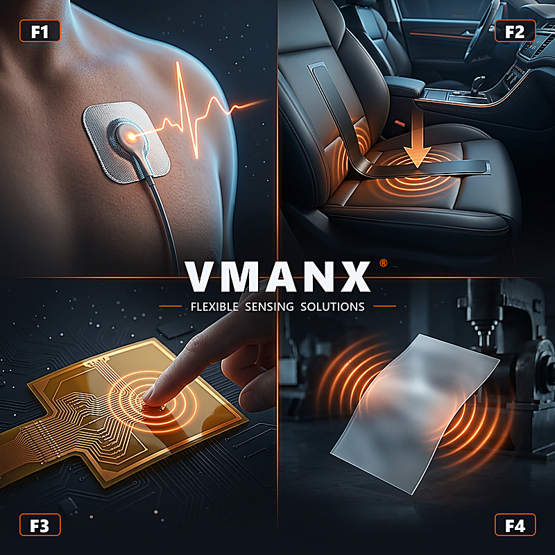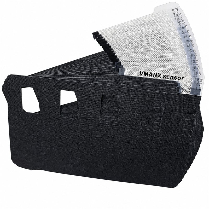
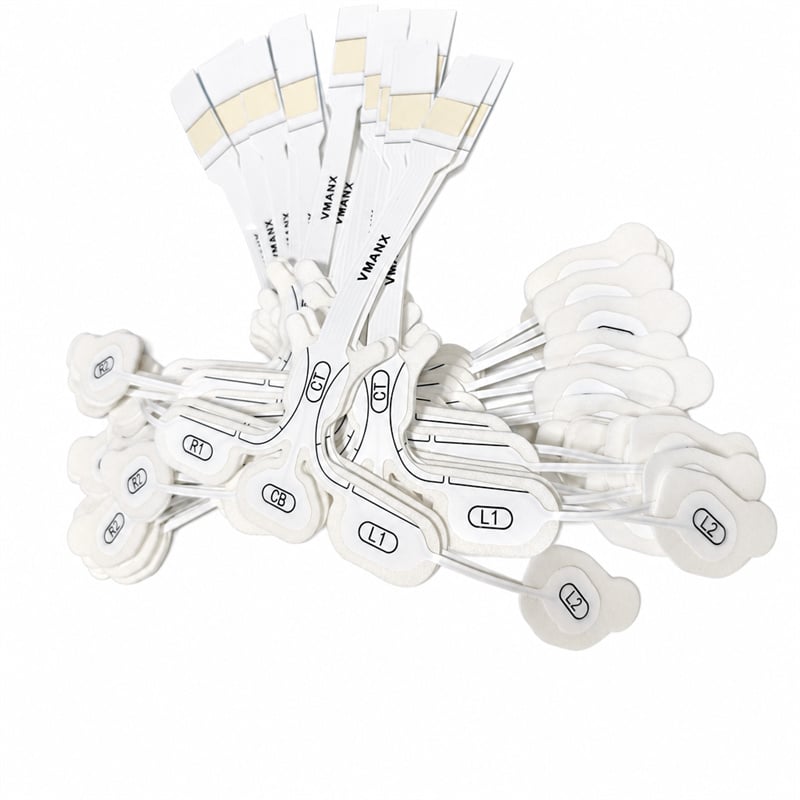
Six-lead pre-wired forehead sensor for continuous EEG acquisition in ICU, operating room, sleep laboratory and ambulatory neurology. Screen-printed Ag/AgCl on a three-layer flexible composite - one peel, one placement, six channels.
WHY THIS BUILD
One carrier. Six channels. No montage guesswork.
A pre-wired forehead array removes the variable that makes cup-electrode EEG slow and operator dependent: where each contact lands.
01 Fixed inter-electrode geometry
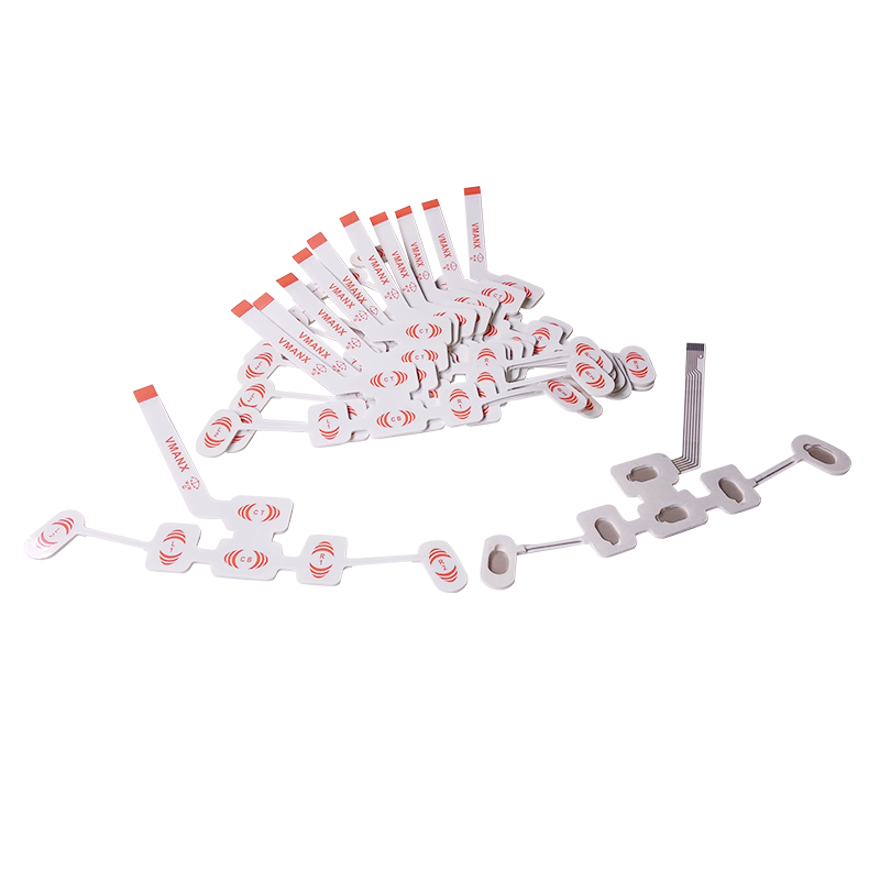
All six leads are die-cut on one carrier, so montage spacing is set at the factory. Placement no longer depends on operator technique.
02 Three-layer flexible composite
PET / PEN substrate, screen-printed Ag/AgCl conductive layer and a skin-contact hydrogel or non-woven layer, laminated in register.
03 Single-piece application
One peel, one placement, one connector insertion. Typical set-up drops from a multi-cup montage to well under a minute.
04 Built for OEM integration
Lead count, tail length, connector pitch, gel chemistry and print artwork are all open to specification.
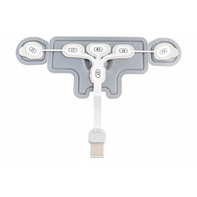
Six identified channels, fixed at the tooling
Lead identification is printed on every branch, so the montage reads the same in every ward and every lot.
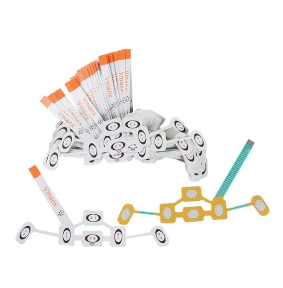
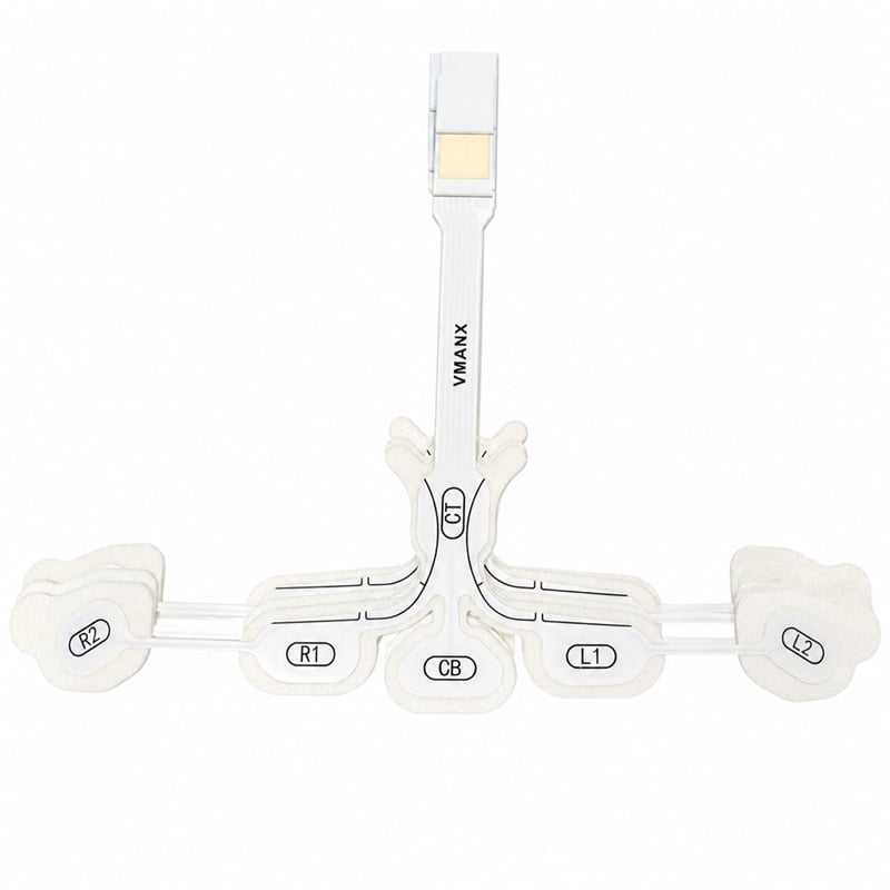
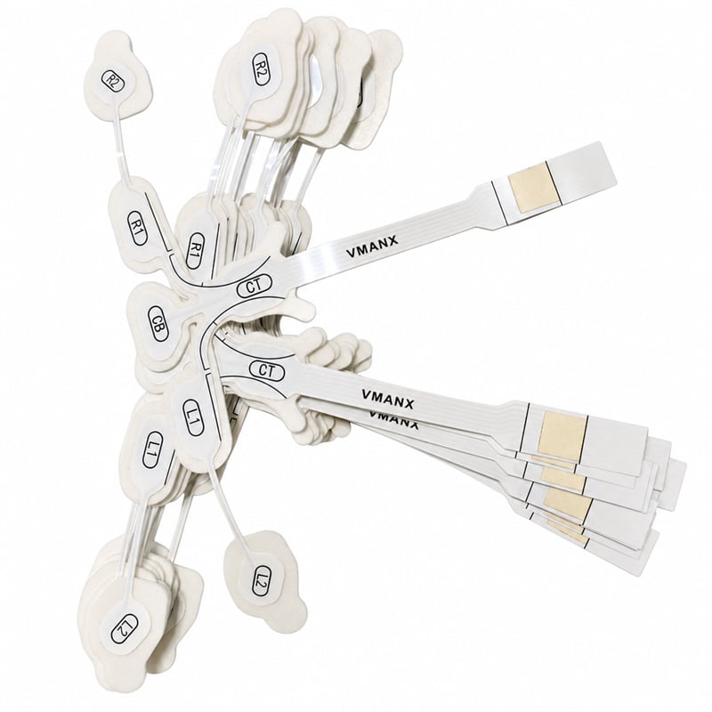
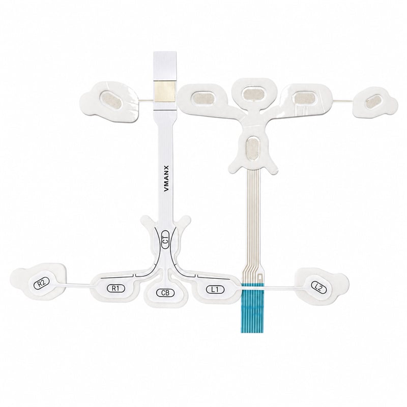
Left: hydrogel sensor build / Right: printed silver-trace FPC build - one shared outline
CHANNEL MAP
CT
Centre top
Common reference / ground tap at the frontal midline
CB
Centre bottom
Second midline contact, glabella region
R1
Right inner
Right frontal channel, inner position
R2
Right outer
Right frontotemporal channel, outer position
L1
Left inner
Left frontal channel, inner position
L2
Left outer
Left frontotemporal channel, outer position
CT is the common reference tap. Channel count and branch spacing are re-cut to the customer montage.
Measured to the ANSI/AAMI EC12 method
The figures below are what an acquisition front end actually sees: offset, drift, contact impedance, noise floor and recovery after a defibrillation discharge.
| PARAMETER | VMANX VA-EEG-900 |
| DC offset voltage | <= 100 mV (typ. <= 20 mV) |
| Combined offset instability & drift | <= 150 uV/s (typ. <= 50 uV/s) |
| AC impedance @ 10 Hz, 100 uA | <= 2 kohm (typ. <= 800 ohm) |
| Defibrillation overload recovery | <= 100 mV, 5 s after discharge |
| Post-defibrillation drift rate | <= 1 mV/s |
| Internal noise, 0.15 - 100 Hz | <= 150 uV p-p (typ. <= 30 uV p-p) |
| DC bias current tolerance | 200 nA, no loss of function |
| Inter-channel impedance match | <= 15 % deviation across the array |
| Conductor resistance, lead to pad | <= 200 ohm per channel, typ. |
PER-LOT SAMPLING
• Incoming
Film, ink and gel lots verified before release to the line.
• In-process
Print registration and trace width checked at set frequency.
• Electrical
Impedance and DC offset sampled to the EC12 method.
• Final
Visual, dimensional and seal integrity before pouching.
A three-layer flexible composite
Printed, die-cut and laminated in register - the stack is what fixes both the electrical behaviour and the wear comfort.
01 Flexible dielectric substrate
PET or PEN film, 75 - 125 um. Laser-registered die-cut outline defines the six-lead geometry and the strain-relief neck at the tail.
02 Screen-printed conductive layer
Ag/AgCl ink printed and cured in a controlled line, then insulated with a dielectric overprint so only the sensing window is exposed.
03 Skin interface layer
Solid conductive hydrogel or wet non-woven pad with a medical pressure sensitive adhesive frame, sized per channel.
04 Termination
Exposed gold or carbon tail contacts on a 1.0 / 1.25 mm pitch, or an over-moulded housing for a keyed, blind-mate connection.
Dimensional, mechanical and handling limits
MECHANICAL / DIMENSIONAL
| Array configuration | 6 leads, single-piece, pre-wired |
| Total laminate thickness | 0.30 - 0.45 mm (0.35 mm typ.) |
| Sensing pad area, per channel | 150 - 320 mm2, per specification |
| Tail length | 150 - 1200 mm, cut to order |
| Tail contact pitch | 1.00 / 1.25 mm, gold or carbon |
| Bend endurance, tail neck | > 5000 cycles at R5 mm, no open circuit |
| Peel adhesion, 180 deg to steel | 4 - 8 N/25 mm, per gel selection |
| Validated wear time | up to 24 h continuous |
ENVIRONMENT / PACKAGING
| Operating temperature | 10 C to 40 C |
| Operating humidity | 30 % to 75 % RH, non-condensing |
| Storage temperature | 5 C to 30 C, foil pouch sealed |
| Shelf life | 18 months from date of manufacture, typ. |
| Sterilisation option | EO or gamma, validated on request |
| Default supply state | Non-sterile, single use, sealed pouch |
| Primary packaging | Foil laminate pouch, desiccant on request |
| Carrier option | Thermoformed PETG tray for automated line feed |
MATERIAL SYSTEM
SUBSTRATE
PET / PEN, halogen-free
CONDUCTIVE SYSTEM
Screen-printed Ag/AgCl
SKIN INTERFACE
Conductive hydrogel or wet non-woven
ADHESIVE
Medical grade acrylic PSA
TAIL CONTACTS
Immersion gold or carbon
HOUSING OPTION
Over-moulded TPE / PP
LATEX CONTENT
Latex free
SUBSTANCE COMPLIANCE
RoHS / REACH declared
Real parts, shipped configurations
Every image below is an actual VMANX build of this platform - not a render. The same die-cut geometry is released in several interface and termination options.
The released baseline build. Six leads on one carrier with the midline CT / CB pair and the paired R1 / R2 and L1 / L2 frontotemporal channels, terminated in an exposed gold tail contact block for a direct ZIF insertion.
• Fixed montage geometry, no operator spacing error
• Printed lead identification on every branch
• Strain-relief neck between array and tail
The same die-cut outline is released in two interface builds: a hydrogel sensor build for wet-contact acquisition, and a fully printed silver-trace build on a flexible circuit tail for direct board-level termination.
• Hydrogel build for standard clinical acquisition
• Printed silver-trace build for FPC-terminated systems
• Common footprint keeps one application procedure
For OEM lines that automate feeding, the array is supplied in a thermoformed carrier with an over-moulded connector housing. The keyed housing makes the mating blind and repeatable at the bedside.
• Keyed over-moulded housing, blind-mate
• Thermoformed PETG tray for pick-and-place feed
• Tray cavity matched to the released outline
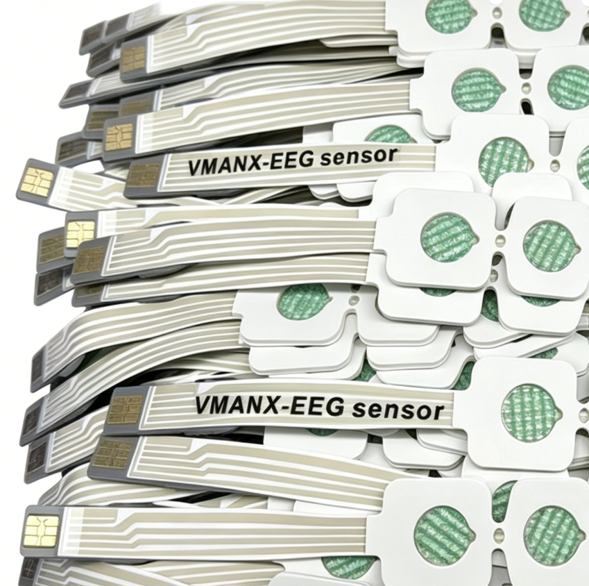
Screen printing, die-cutting and lamination run on registered tooling, so the sensing window position and the printed trace width repeat across the lot. Impedance and offset are sampled per lot before release.
• Registered tooling, repeatable sensing window
• Per-lot impedance and DC offset sampling
• Full lot traceability from the line batch to pouch
Where a pre-wired frontal array earns its place
ICU —— Continuous bedside EEG
Long-run monitoring of sedated and critical-care patients without a full cap montage.
SLEEP LAB —— Polysomnography
Low-profile frontal acquisition that stays applied through a full overnight study.
OPERATING ROOM —— Depth-of-anaesthesia
Fast single-piece placement at induction, with a keyed connection to the anaesthesia module.
NEUROLOGY —— Ambulatory screening
Belt-worn recorder workflows where the patient leaves the clinic wearing the sensor.
What we open up to specification
This is a component platform, not a catalogue item. The items below are routinely re-cut for a customer released drawing.
Lead count & montage
Channel count, spacing and branch geometry re-cut to the customer montage.
Tail & termination
Length, pitch, contact metallisation, FPC stiffener or over-moulded housing.
Skin interface
Gel chemistry, adhesive tack and pad area tuned to wear time and skin type.
Print & identification
Customer artwork, lead marking, lot and UDI field printed in line.
Packaging
Pouch, tray, kitting and labelling to the customer released drawing.
Documentation
Drawing pack, per-lot test record and biocompatibility evidence under ISO 10993.
Certified where it counts, honest about the rest
ISO 13485:2016
Medical QMS
ISO 10993
Biocompatibility
RoHS / REACH
Substance Compliance
VMANX supplies this product as an OEM component. ISO 13485:2016 covers the VMANX quality management system and ISO 10993 covers biocompatibility evaluation of the patient-contacting materials. Registration, clinical validation and market approval of the finished medical device remain the responsibility of the legal manufacturer placing that device on the market. Typical values are production means, not guaranteed limits; the released specification governs. Specifications are subject to change without notice.

Dongguan Zhongman Industrial Co., Ltd.
 EN
EN